Optical water surface detector and method

a detector and optical technology, applied in the field of optical water surface detectors and methods, can solve the problems of inability to achieve the level of accuracy and subjectivity of the process technician, and achieve the effect of increasing the time required for positioning the chamber

Active Publication Date: 2017-05-18
AKTINA CORP
View PDF8 Cites 1 Cited by
  • Summary
  • Abstract
  • Description
  • Claims
  • Application Information

AI Technical Summary

Benefits of technology

[0008]Step A is very subjective and difficult to accomplish accurately due mainly to water meniscus and parallax effects. The subjective nature of the process means that users typically doubl

Problems solved by technology

This device and method completely removes the technician's subjectivity from the proces

Method used


Image

  • Optical water surface detector and method
  • Optical water surface detector and method
  • Optical water surface detector and method

Examples


Embodiment Construction

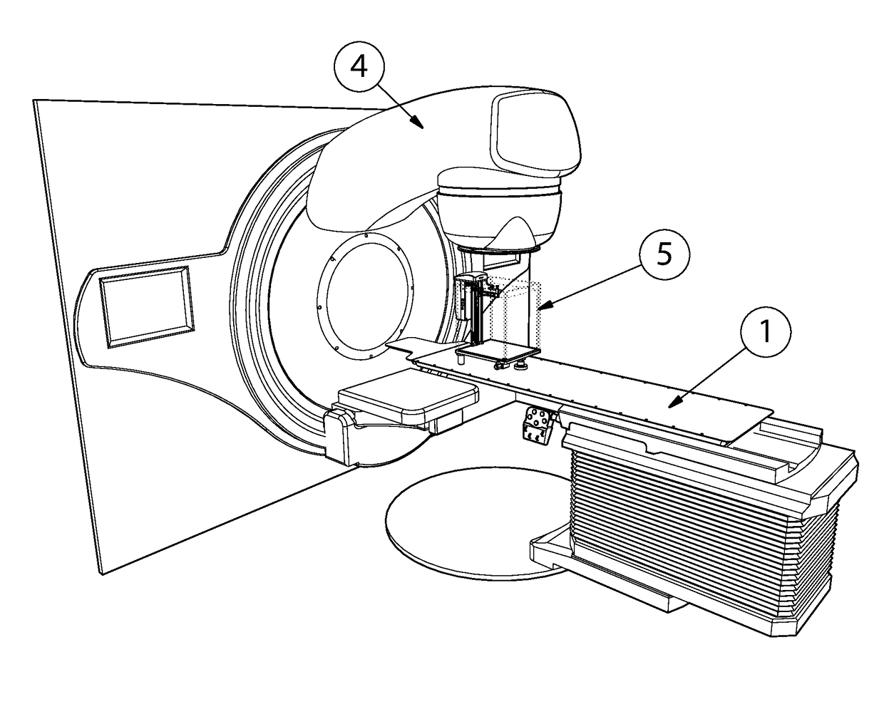
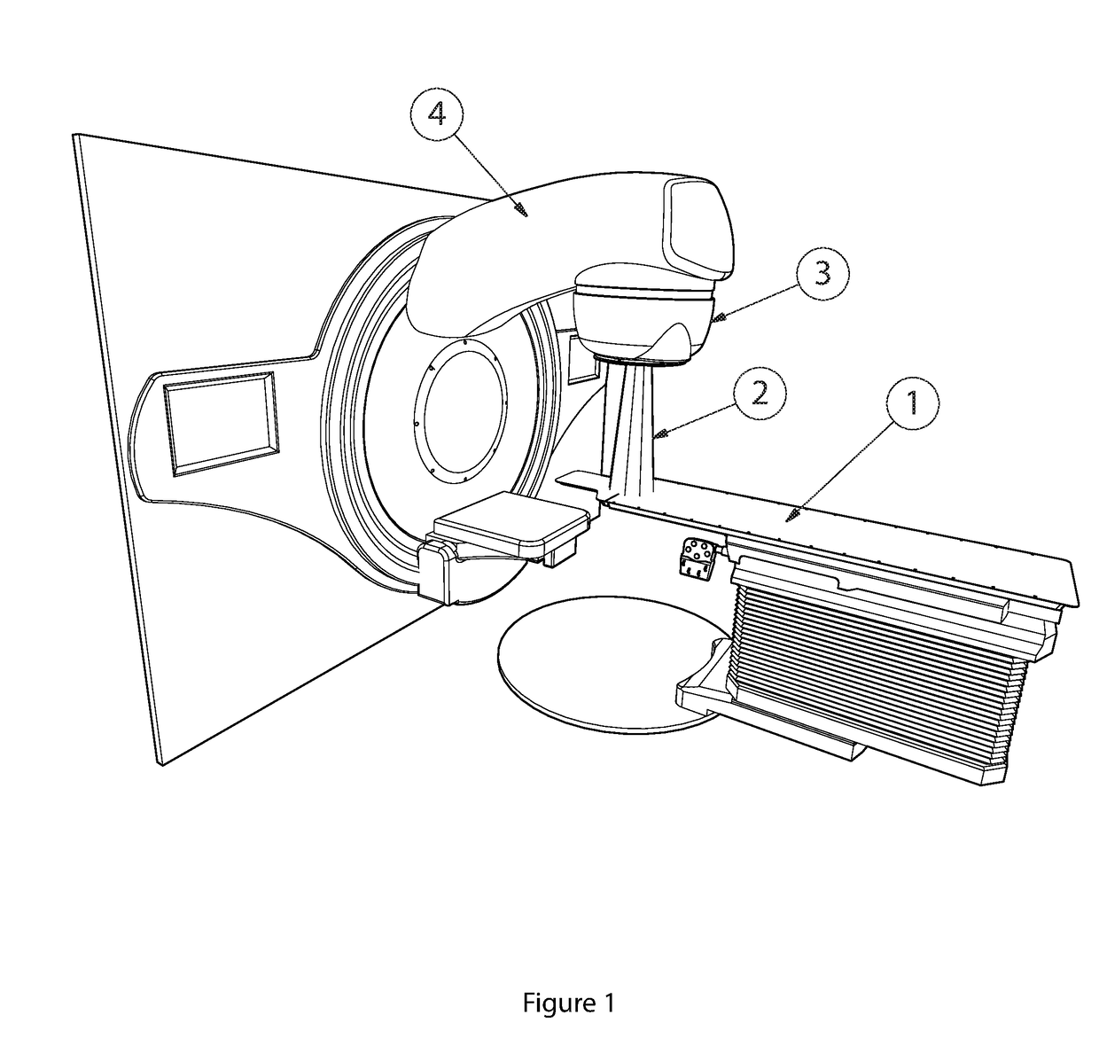
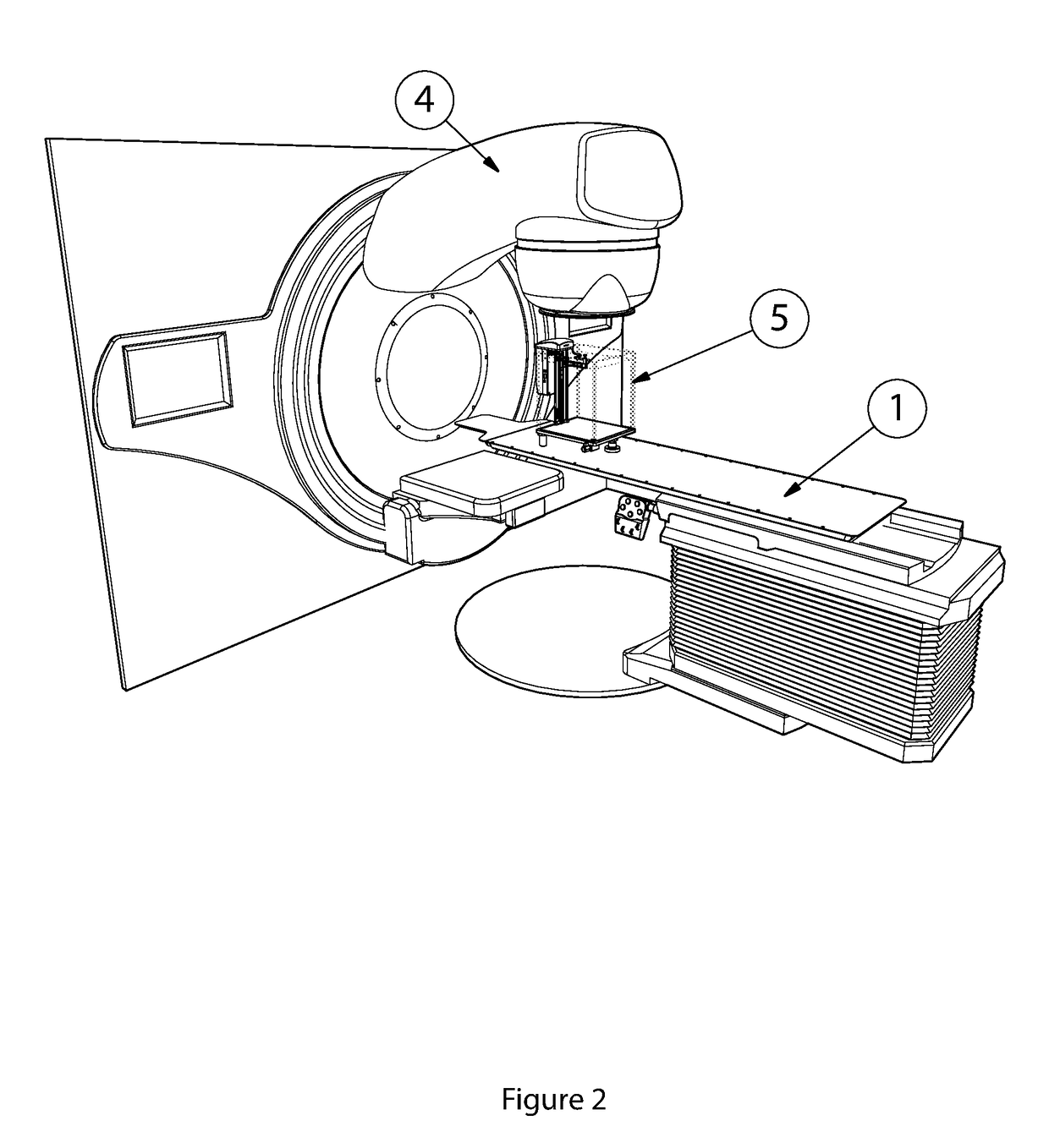
[0050]As shown on FIG. 6 the optical water surface detector consists of a light source, such as an infra-red transmitter, assembly (16) and a corresponding light detector receiver (light receiver) assembly (18) that is housed within a light and receiver housing. The light and receiver unit can be a single unit or comprised of an upper body (17) and lower body (19) as shown on the figures. The optical water surface detector device is mounted on an arm (10) attached to a positioning mechanism (11) within a water tank such as a water tank phantom (5).

[0051]A main control unit is typically mounted on the tank but can be mounted separate from the water tank. The device is connected to a microprocessor located in the main control unit (7) via a signal cable (20) and connector (21). The main control unit controls the positioning mechanism and the optical water surface detector. A mechanism, such as leveling feet (13), is provided on the water tank to ensure the tank is level. And a level c...


PUM


Abstract

A device and method to be used in the calibration process for a linear accelerator (LINAC). The optical water surface detector device allows the accurate determine of the height of the water surface in a tank. The device housing includes a light source and a light receiver. The housing can also include a circuit board. The device is mounted on an arm attached to a vertical position mechanism mounted within the tank. The light source within the device is controlled by a main control unit which also receives signals from the receiver and determines the amount of light striking the receiver. The control unit also controls the position of the vertical position mechanism and thus the arm on which the device is mounted.

Description

CROSS-REFERENCE TO RELATED APPLICATION[0001]This non-provisional application claims priority from pending provisional Application No. 62 / 255,563 filed in the United States Patent and Trademark Office on Nov. 16, 2015.BACKGROUND OF THE INVENTION[0002]A medical linear accelerator (LINAC) is a common tool used within oncology community in the fight against cancer. (FIG. 1) These devices deliver targeted radiation to the tumor sight in an accurate and reproducible manner. Routine quality control (QC) is required on the LINAC to ensure that (A) the LINAC is delivering the correct amount of radiation and (B) the LINAC is directing the radiation to the correct location within the patient.[0003]The tests that are used to monitor the amount of radiation given typically involve measuring the radiation output delivered to a device that simulates the patient. These devices, referred to as phantoms, are usually water filled tanks with robotics that position a radiation measuring sensor at variou...

Claims


Application Information

Patent Timeline
IPC IPC(8): A61N5/10G01J1/42
CPCA61N5/1075A61N2005/1076G01J1/42G01F23/2928G01F25/20G01T1/169
Inventor ZACHAROPOULOS, NICHOLAS G.
Owner AKTINA CORP
Why Eureka
Try Eureka