Patient transport vehicle flooring panel with built-in anti-slip tread

a technology for passenger transportation vehicles and flooring panels, applied in the field of modular flooring systems, can solve the problems of affecting the balance and performance of patient transport aircraft, affecting the treatment effect of patients or patients, and not well-planned space, so as to reduce the weight of the flooring panel

Active Publication Date: 2015-09-08
AIR METHODS
View PDF8 Cites 13 Cited by
  • Summary
  • Abstract
  • Description
  • Claims
  • Application Information

AI Technical Summary

Benefits of technology

[0010]The bottom portion of the panel may include a plurality of support members extending away from the top portion and that are adapted to carry a load received on the top surface and transfer the load to the base platform of the vehicle and / or the underlying frame or structure of the vehicle. In one arrangement, a first portion of the plurality of support members may be adapted to support a first predetermined load, a second portion of the plurality of support members spaced from the first plurality may be adapted to support a second predetermined load, and where the first predetermined load is different than the second predetermined load. Additionally, the bottom portion may include a plurality of cavities disposed between adjacent pairs of the plurality of support members that serve to reduce the weight of the flooring panel.
[0011]In another aspect, a flooring system for use in overlaying a base platform of a vehicle is disclosed that includes a first flooring panel (e.g., the above-discussed flooring panel) having a top portion, a bottom portion, and a peripheral edge having a first interface portion; and a second flooring panel (e.g., the above discussed flooring panel) having a top portion, a bottom portion, and a peripheral edge having a second interface portion. The first and second interface portions are removably interfaceable with each other at an interface region in a manner that allows the top surface of the first flooring panel to be substantially level with the top surface of the second flooring panel while limiting passage of fluids through the interface region.

Problems solved by technology

Aircraft interior space that is not well-planned with respect to emergency equipment location, patient location, attendant accessibility to both the equipment and the patient, access to wiring, and the like can be a detriment to effectively treating the patient or patients.
Specifically, aircraft components that are unnecessarily heavy may detrimentally affect the balance and performance of a patient transport aircraft.

Method used


Image

  • Patient transport vehicle flooring panel with built-in anti-slip tread
  • Patient transport vehicle flooring panel with built-in anti-slip tread
  • Patient transport vehicle flooring panel with built-in anti-slip tread

Examples


Embodiment Construction

[0041]Reference will now be made to the accompanying drawings, which assist in illustrating the various pertinent features of the various novel aspects of the present disclosure. In this regard, the following description is presented for purposes of illustration and description. Furthermore, the description is not intended to limit the inventive aspects to the forms disclosed herein. Consequently, variations and modifications commensurate with the following teachings, and skill and knowledge of the relevant art, are within the scope of the present inventive aspects.

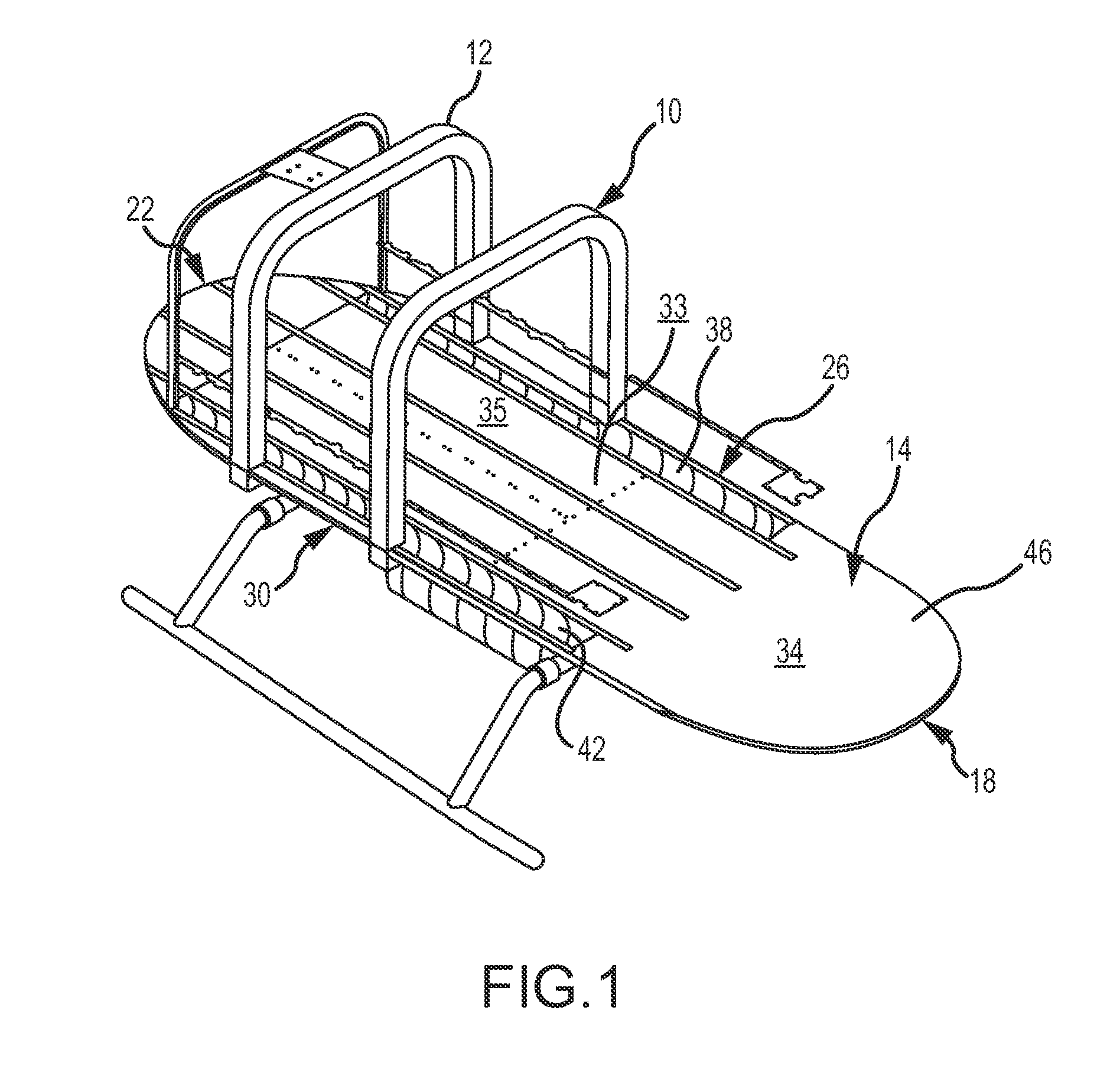
[0042]FIG. 1 is a perspective view of an emergency transport vehicle 10 (e.g., an aircraft such as a helicopter) according to one embodiment. The vehicle 10 may generally include any appropriate frame structure 12, a base platform 14 having an upper surface 46, and a cabin 33 including an operator (e.g., pilot) area 34 (e.g., including cockpit seats, controls, etc.), a passenger and equipment area 35 (e.g., including seat...


PUM

PropertyMeasurementUnit
angleaaaaaaaaaa
areaaaaaaaaaaa
pyramid shapeaaaaaaaaaa

Abstract

A flooring system positionable over a base platform in the cabin of a vehicle such as an aircraft. In one embodiment, the flooring system includes one or more flooring panels each having top and bottom portions, where the top portion defines a top surface including an anti-slip tread. Additionally or alternatively, the flooring system may be made up of a plurality of flooring panels that are adapted to meet at respective interface regions so as to limit fluid passage through the interface regions. In one arrangement, one flooring panel may be separated from an adjacent flooring panel to expose a wiring trough underneath the one flooring panel free of separating the adjacent flooring panel from the aircraft base platform.

Description

RELATED APPLICATIONS[0001]This application claims priority to U.S. Provisional Patent Application No. 61 / 597,733, filed Feb. 11, 2012, entitled “MODULAR FLOORING SYSTEM FOR A PATIENT TRANSPORT VEHICLE,” which application is incorporated herein by reference in its entirety.FIELD OF THE INVENTION[0002]This invention generally relates to a flooring system for use in a vehicle and, more particularly, to a modular flooring system that is positionable over a base platform of a patient transport vehicle.BACKGROUND OF THE INVENTION[0003]The air-medical industry has long recognized the importance of providing effective medical attention to a patient during transport of the patient from the emergency site to a permanent medical facility. Aircraft interior space that is not well-planned with respect to emergency equipment location, patient location, attendant accessibility to both the equipment and the patient, access to wiring, and the like can be a detriment to effectively treating the patie...

Claims


Application Information

Patent Timeline
Patent Type & Authority Patents(United States)
IPC IPC(8): B32B3/00B64C1/18
CPCB64C1/18Y10T428/24174Y10T428/24182Y10T428/24273
Inventor GREEN, LOWELLFISHER, JIM
Owner AIR METHODS
Why Eureka
Try Eureka