Atmospheric turbulence isolation system and method

a technology of atmospheric turbulence and isolation system, which is applied in the direction of shock absorbers, machine supports, transportation and packaging, etc., can solve the problems of significant aerodynamic turbulence in the fuselage area, aerodynamic turbulence manifesting as pressure fluctuations, and exposing the turret assembly to undesirable aerodynamic effects, so as to reduce the time-averaged energy density and prevent the effect of beam jittering

Inactive Publication Date: 2015-09-08
THE BOEING CO
View PDF8 Cites 0 Cited by
  • Summary
  • Abstract
  • Description
  • Claims
  • Application Information

AI Technical Summary

Benefits of technology

[0011]In one embodiment, the vibration isolation assembly may comprise a rigid outer layer disposed in spaced relation to an outer surface of the aerodynamic object and having a viscoelastic inner layer disposed between the rigid outer layer and the aerodynamic object. In this manner, the vibration isolation assembly provides an isolation and damping of vibration which may otherwise be transmitted to sensitive components such as the above-described electronics and optical systems and other instrumentation.
[0012]In one embodiment, the aerodynamic object may be configured as a turret assembly which may be disposed on a vehicle such as an aircraft. The turret assembly may be located on an underside of a fuselage of the aircraft. The turret assembly may comprise an inner gimbal subassembly rotationally mounted to an outer gimbal subassembly which, in turn, may be rotationally mounted to an optical system that may be contained within the aircraft. The outer gimbal subassembly may be configured to rotate laterally or in azimuth (e.g., in a horizontal plane) while the inner gimbal subassembly may be configured to rotate vertically or in elevation (e.g., in a vertical plane) such that the turret assembly provides a spherical range of motion to a system such as a pointing device. In this regard, the vibration isolation assembly provides a low-cost passive system for preventing or reducing the transmission of vibration induced by aerodynamic buffeting or loading on the aerodynamic object into sensitive electronics or optical systems contained within the aerodynamic object.
[0013]The technical effects of the disclosed embodiments include a reduction in the transmission of aerodynamically-induced vibration of the aerodynamic object without interfering with the functionality of the components that may be mounted within the aerodynamic object. The vibration isolation assembly provides a passive system which is simple in construction and low in cost. Furthermore, the vibration isolation assembly may be tuned in accordance with a natural frequency or resonant frequency (e.g., isolation frequency) of the system (e.g., mounting platform of optics and electronics) by material selection and / or sizing of inner and outer layers which make up the vibration isolation assembly.
[0014]In one embodiment, the outer layer may be configured as a continuous rigid layer mounted over a viscoelastic inner layer which, in turn, may be applied to the outer surface of the aerodynamic object. Alternatively, either one or both of the inner and outer layers may be configured as a plurality of segments which are applied to the aerodynamic object. The segments may define a plurality of gaps between adjacent segments to prevent lateral transmission of vibration.
[0017]In one embodiment, the pointing device may be configured as a beam director for a laser wherein a window mounted on the inner gimbal subassembly may be rotated into any position for projection of a laser beam through the window. In this regard, the vibration isolation assembly as disclosed herein may prevent the transmission of mechanical vibration from the outer layer to the beam director in order to prevent jittering of the beam which may reduce the time-averaged energy density applied to a target by the beam.
[0018]The inner and outer layers are preferably sized and configured to attenuate vibration occurring above a predetermined isolation frequency. For example, the inner and outer layers may be sized and configured to attenuate vibration of sensitive electronics at frequencies of greater than approximately 1.4 times the isolation frequency. In a preferable embodiment, the inner and outer layers are preferably sized and configured such that at frequencies of approximately 5 times the isolation frequency, the amount of vibration that is transmitted to the sensitive electronics may be reduced by approximately 50% and, in a more preferable embodiment, may be reduced by approximately 80%. Tailoring of the configuration of the outer layer and the viscoelastic inner layer permits the selection of the isolation frequency and may therefore provide a desired level of vibration isolation of the sensitive electronics and optics in a frequency range of highest sensitivity.

Problems solved by technology

Although mounting on the underside of the fuselage provides certain operational advantages, such location exposes the turret assembly to undesirable aerodynamic effects.
For example, significant aerodynamic turbulence may be present in the fuselage area where the turret assembly is mounted due to interactions between the air flow and the turret assembly and aircraft.
Such aerodynamic turbulence is manifested as pressure fluctuations that may be non-uniformly and / or non-synchronously imposed on the turret assembly.
Additionally, the turret assembly may produce additional aerodynamic turbulence and pressure fluctuations due to flow separation aft of the turret assembly as well as due to specific configuration features of the turret assembly that create local flow separation.
Unfortunately, such non-uniform loading on the turret assembly induces vibration which is transmitted to sensitive electronics and optics contained within the turret assembly.
Such vibrations affect the performance of the optics and electronics and thereby affects the precision with which the laser may be projected to a target.
In this regard, vibrations induced by aerodynamic loading on an outer surface of the turret assembly and which are transmitted to the beam director result in jittering of the laser beam which, when projected onto a target, minimizes the energy density with which the laser may be applied to the target.
Unfortunately, the turret-in-turret approach requires duel-nested deployment mechanisms with isolated load paths to prevent the transmission of vibration to the instrumentation.
Because of the duel-nested deployment mechanisms, the turret-in-turret approach is relatively complex and results in a configuration that is relatively high in weight, cost and volume, and requiring a high degree of maintenance.

Method used


Image

  • Atmospheric turbulence isolation system and method
  • Atmospheric turbulence isolation system and method
  • Atmospheric turbulence isolation system and method

Examples


Embodiment Construction

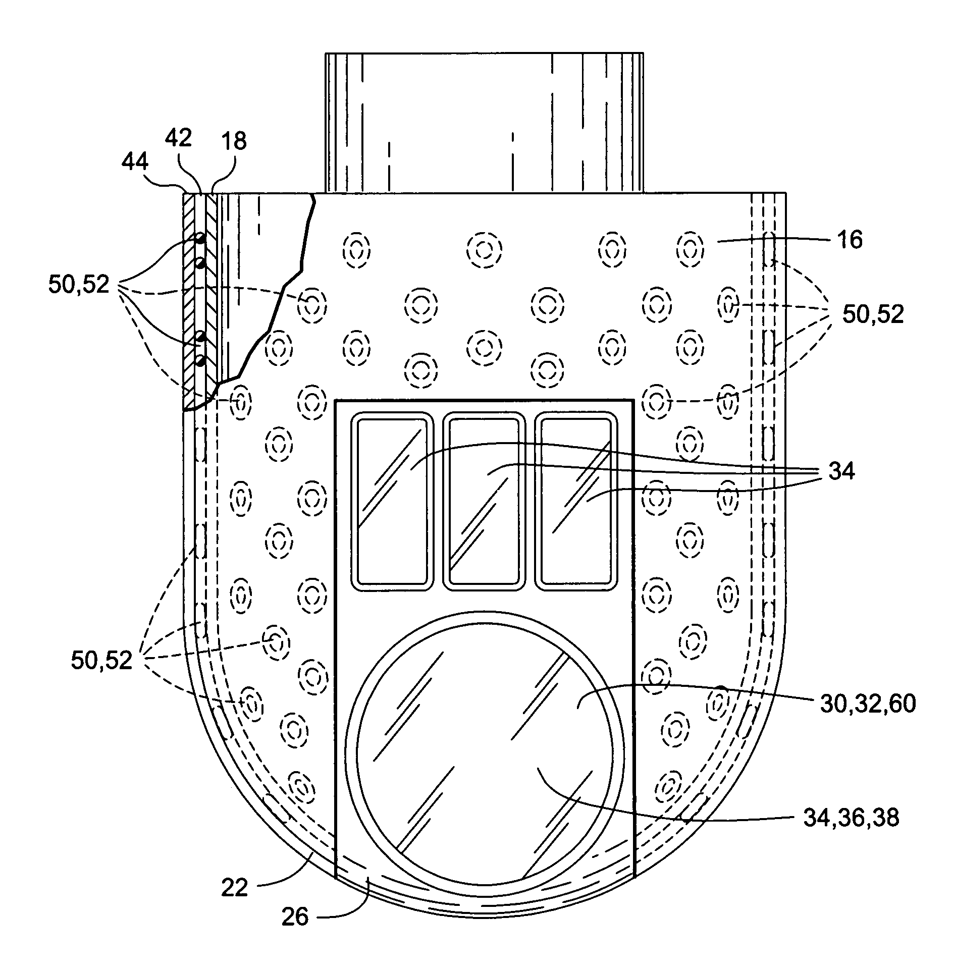
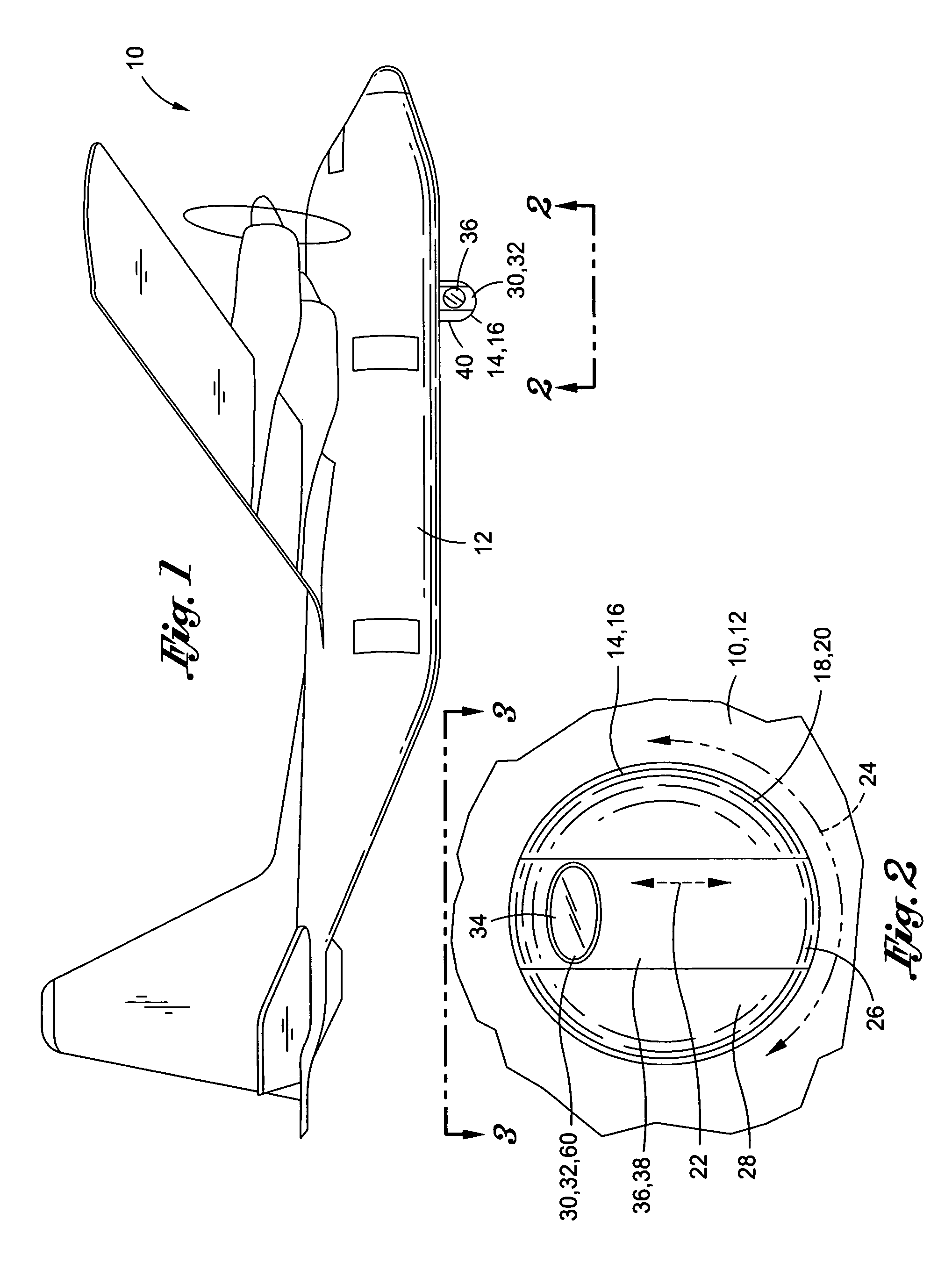
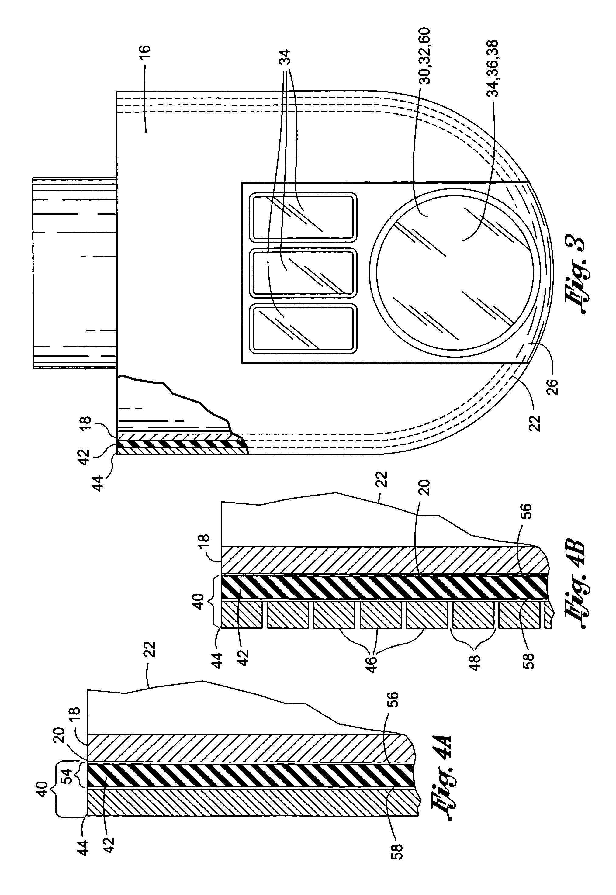
[0029]Referring now to the drawings wherein the showings are for purposes of illustrating various embodiments of the disclosure only and not for purposes of limiting the same, shown in FIG. 1 is an aircraft 10 having an aerodynamic object 14 which is illustrated and described herein for exemplary purposes only as a turret assembly 16. The turret assembly 16 is shown mounted to a lower side of a fuselage 12 of the aircraft 10 although the turret assembly 16 or aerodynamic object 14 may be mounted at any location on any type of vehicle. Housed within the turret assembly 16 may be a variety of systems such as optical systems 32 and electronics systems 60 for a beam director 38 as may be used in a laser 36 system.

[0030]Advantageously, the turret assembly 16 may include a vibration isolation assembly 40 as disclosed herein for attenuating aerodynamic loads which may otherwise induce vibration of a system 30 that may be mounted within or which may form a part of the turret assembly 16. Un...


PUM


Abstract

A vibration isolation assembly for an aerodynamic object comprises a viscoelastic inner layer disposed on the aerodynamic object and being configured to attenuate vibration. The vibration isolation assembly further comprises a rigid or stiff outer layer disposed on an inner layer. The vibration isolation assembly may attenuate the transmission of aerodynamically-induced vibration to components contained or mounted to the aerodynamic object.

Description

STATEMENT RE: FEDERALLY SPONSORED RESEARCH / DEVELOPMENT[0001]This invention was made with Government support under Contract No. F29601-03-C-0146 awarded by the Air Force. The government has certain rights in this invention.CROSS-REFERENCE TO RELATED APPLICATIONS[0002](Not Applicable)FIELD[0003]The present invention relates generally to vibration isolation and, more particularly, to a vibration isolation assembly specifically adapted to reduce aerodynamic pressure fluctuations which induce vibration in an aerodynamic object.BACKGROUND[0004]For systems containing sensitive instrumentation, it is typically desirable to minimize vibration such that the instrumentation may perform at an optimal level while avoiding damage to the instrumentation. For example, in tactical weapons such as airborne lasers mounted on aircraft, a beam director is typically included for controlling the direction along which a laser beam is projected to a target. The beam director may include a turret assembly to...

Claims


Application Information

Patent Timeline
Patent Type & Authority Patents(United States)
IPC IPC(8): B64D47/08B64C1/40F16F9/30
CPCB64D47/08B64C1/40F16F9/306
Inventor ULLMAN, ALAN Z.GRIFFIN, STEVEN F.
Owner THE BOEING CO
Why Eureka
Try Eureka