
Evaporator

a technology of evaporator and heat exchanger, which is applied in the direction of indirect heat exchangers, refrigeration components, light and heating apparatus, etc., can solve the problems of limitation of shape or general dimensions, deterioration limitation of heat exchange performance, so as to maximize the heat radiation amount, reduce the deviation of the maximum temperature, and flow smoothly

Active Publication Date: 2015-09-08
HANON SYST
View PDF27 Cites 0 Cited by
  • Summary
  • Abstract
  • Description
  • Claims
  • Application Information

AI Technical Summary

Benefits of technology

[0018]Therefore, by optimizing a relation between the surface area of the communication portion and the surface area of the compartment of the first header tank and dimensions for each surface area and the heights of the tube and fin, the present invention provides a dimensional extent for maximizing the heat radiation amount, reducing the maximum temperature deviation of the core portion and allowing the refrigerant and air to be smoothly flowed, thereby maximizing the heat exchange efficiency.

Problems solved by technology

Thus, if a height of the tube is high, the internal refrigerant is smoothly flowed, but since a height of the external fin is reduced and thus the flow of external air is restricted, the heat exchange performance is deteriorated.
However, if the height of the tube is low, the external air can be smoothly flowed, but the flow of internal refrigerant is restricted and thus the heat exchange performance is deteriorated.
However, in the conventional evaporator, there was provided only limitation of its shape or general dimensions, and there was never provided a detailed dimensional extent such as the surface area of the communicating hole and the number of the communicating holes considering the flow of refrigerant, and the height and the surface area of the fin and tube and a density of the fins considering a pressure drop amount of the refrigerant and the like.

Method used


Image

  • Evaporator
  • Evaporator
  • Evaporator

Examples


Embodiment Construction

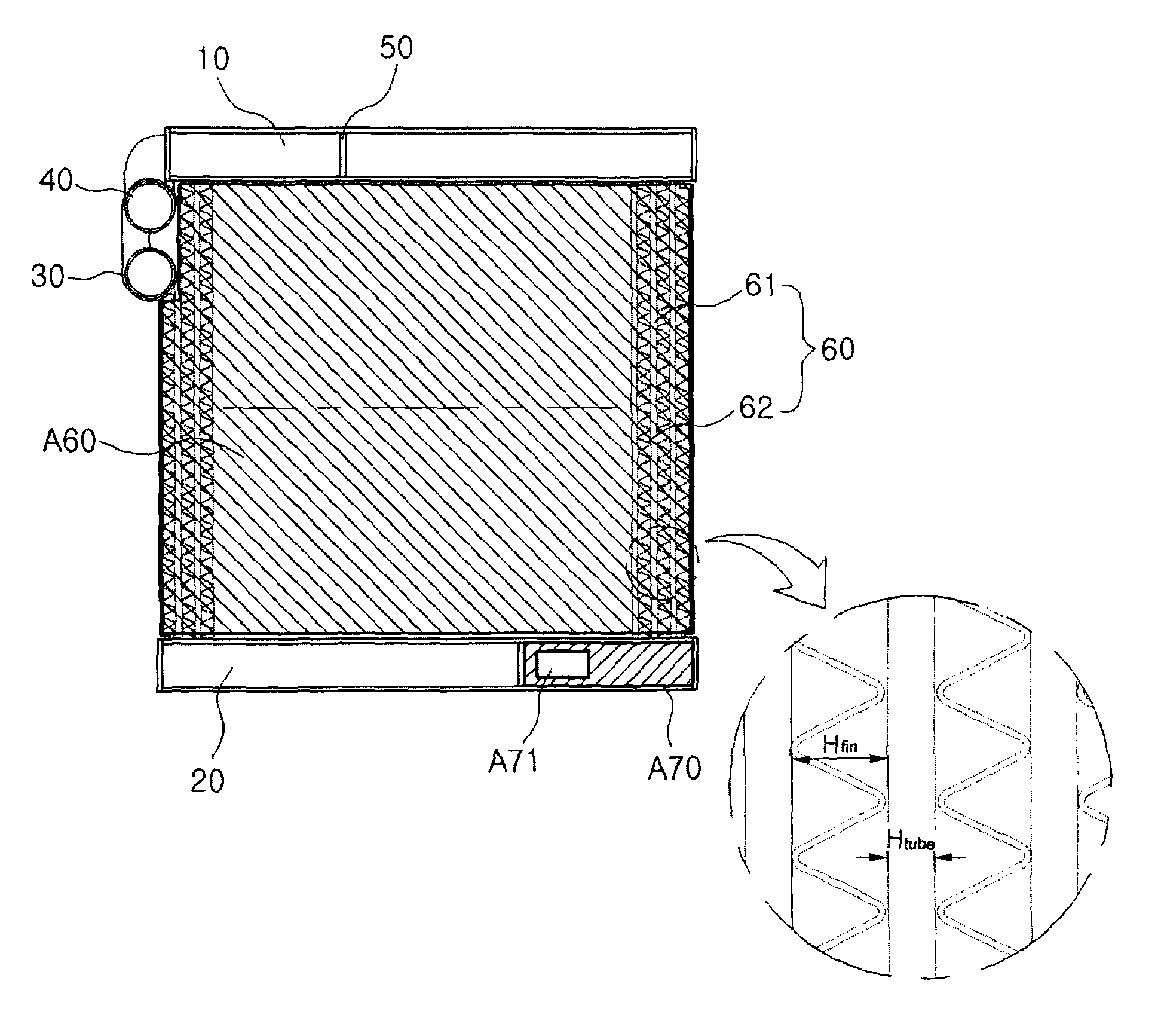
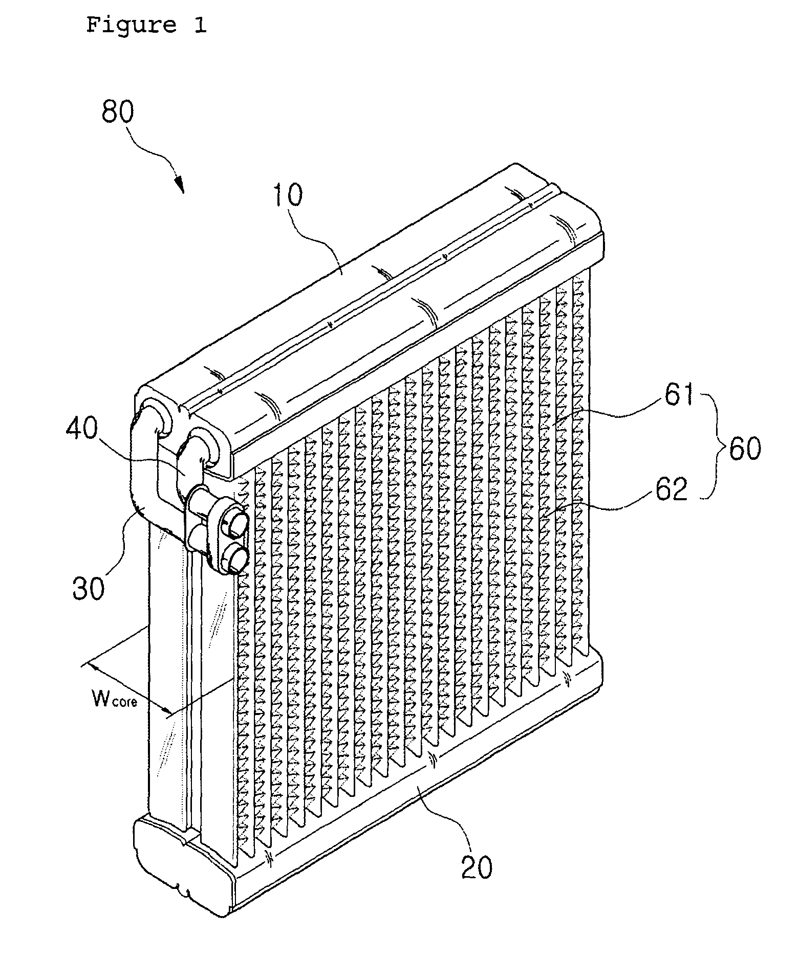
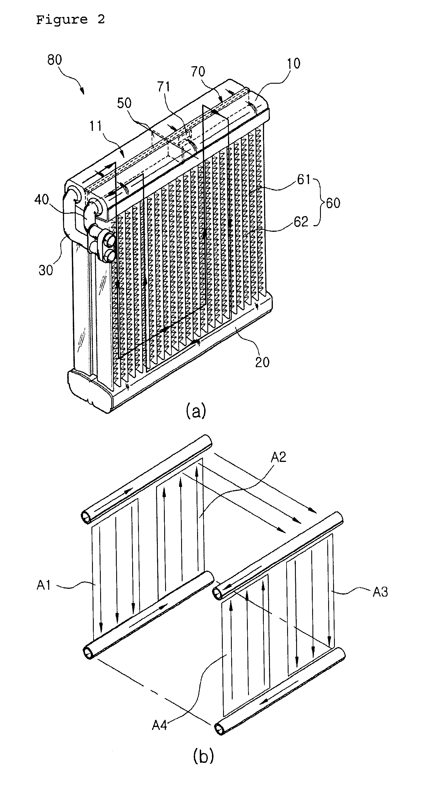
[0038]10: first header tank[0039]11: compartment[0040]20: second header tank[0041]30: inlet pipe[0042]40: outlet pipe[0043]50: baffle[0044]60: core portion[0045]61: tube[0046]62: fin[0047]70: communication portion[0048]71: communicating hole[0049]80: evaporator of the present invention[0050]A1˜A4: each region of evaporator[0051]A70: surface area of communication portion[0052]A71: surface area of communicating hole[0053]A60: surface area of core portion[0054]A61: surface area of tube[0055]A62: surface area of fin[0056]A11′: cross sectional area of compartment communicated with first row of first header tank[0057]Wcore; width of core portion[0058]Hfin: height of fin[0059]Htube: height of tube[0060]Dfin: density of fins

[Best Mode]

[0061]Hereinafter, the embodiments of the present invention will be described in detail with reference to accompanying drawings.

[0062]FIG. 1 is a perspective view of an evaporator 80 according to the present invention. The evaporator 80 of the present inventio...


PUM


Abstract

The present invention relates to an evaporator, and more particularly, to an evaporator which can restrict a surface area of a communication hole with respect to a cross sectional area of a compartment and a surface area of a tube with respect to a surface area of a fin, thereby providing a dimensional extent for maximizing the heat exchange efficiency. Therefore, by optimizing a relation between the surface area of the communication portion and the surface area of the compartment of the first header tank and dimensions for each surface area and the heights of the tube and fin, the present invention provides a dimensional extent for maximizing the heat radiation amount, reducing the maximum temperature deviation of the core portion and allowing the refrigerant and air to be smoothly flowed, thereby maximizing the heat exchange efficiency.

Description

RELATED APPLICATIONS[0001]The present application is based on, and claims priority from, KR Application No. 10-2007-0089014, filed Sep. 3, 2007, and PCT Application No. PCT / KR08 / 005013, filed Aug. 27, 2008, the disclosures of which are hereby incorporated by reference herein in their entireties.TECHNICAL FIELD[0002]The present invention relates to an evaporator, and more particularly, to an evaporator which can restrict a surface area of a communication hole with respect to a cross sectional area of a compartment and a surface area of a tube with respect to a surface area of a fin, thereby providing a dimensional extent for maximizing the heat exchange efficiency.BACKGROUND ART[0003]In the recent automotive industry, according as the global interest in environment and energy is increased, there has been performed research and development in the improvement of fuel efficiency. And, in order to satisfy various users' requirements, there has been also proceeded research and development...

Claims


Application Information

Patent Timeline
Patent Type & Authority Patents(United States)
IPC IPC(8): F28D1/053F25B39/02F28F9/02F28F9/22
CPCF28D1/05391F25B39/022F28F9/0204F28F9/028F25B2500/01B60H1/32F28F9/00
Inventor LIM, HONG-YOUNGOH, KWANG HUNJEON, YOUNG-HA
Owner HANON SYST
Learn More