Feeding mechanism for lathe

A technology of tool-feeding mechanism and lathe, which is applied in the direction of turning equipment, accessories of tool holders, metal processing machinery parts, etc., and can solve problems such as difficulty in tool maintenance, reduced precision of workpiece processing, and generation of waste products, etc.

Inactive Publication Date: 2018-11-23
黄红兵
View PDF0 Cites 7 Cited by
  • Summary
  • Abstract
  • Description
  • Claims
  • Application Information

AI Technical Summary

Problems solved by technology

[0005] Aiming at the deficiencies in the prior art, the purpose of the present invention is to provide a lathe tool feed mechanism to solve the problem of manual adjustment of feed or excessive feed of numerical control programming when the lathe of the prior art is started to process workpieces. When the tool is excessively fed and collides with the workpiece, the head of the tool is damaged or even collapsed, making it difficult to maintain the tool and reduce the machining accuracy of the workpiece. When the tool is stopped for protection at the moment of the tool collision, the working Personnel fail to notice and work again, causing the workpiece to produce waste products under tool processing after tool collision

Method used


Image

  • Feeding mechanism for lathe
  • Feeding mechanism for lathe
  • Feeding mechanism for lathe

Examples


Embodiment Construction

[0025] In order to make the technical means, creative features, goals and effects achieved by the present invention easy to understand, the present invention will be further described below in conjunction with specific embodiments.

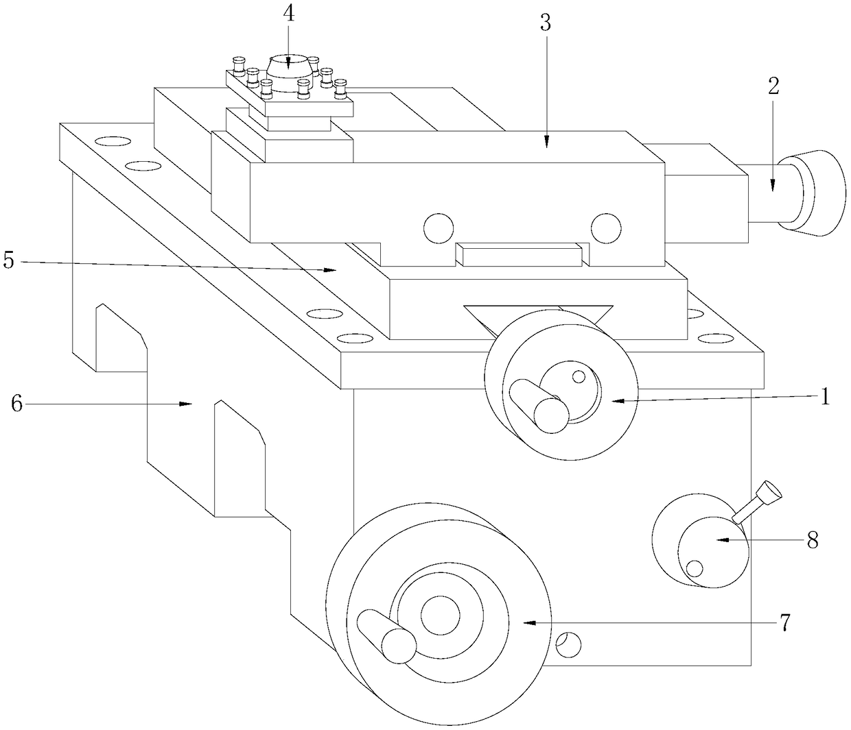
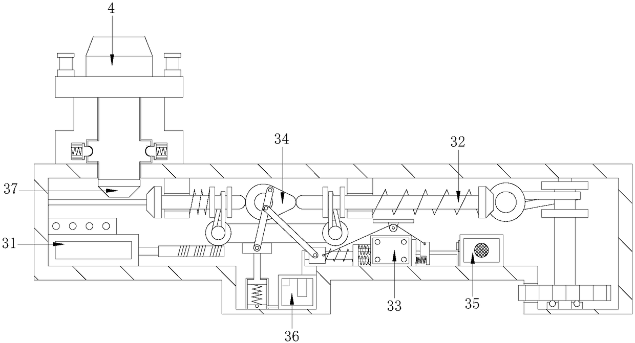
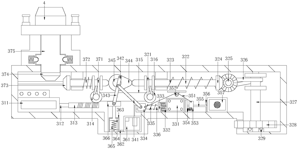
[0026] Such as Figure 1-Figure 5 As shown, the present invention provides a technical scheme of a lathe tool feeding mechanism:

[0027] A tool feed mechanism for a lathe, the structure of which includes a manually adjustable tool feed rotating disc 1, a threaded pipe for tapping 2, a turning feed tool changer 3 for self-stopping anti-collision tools, a turning tool holder 4, a feed guide rail plate 5, and a cutting depth Moving device 6, depth of cut adjustment rotating disc 7, position lock valve 8, the manual adjustment tool feed rotating disc 1 is installed on the front end of the cutting depth moving device 6 and connected by embedding, the tapping pipe 2 is located The right side of the turning feed tool changer 3 of the self-stopping anti...


PUM


Abstract

The invention discloses a feeding mechanism for a lathe. The feeding mechanism structurally comprises a manually-adjusted feeding rotary disc, a tapping tube, a turning and feeding cutter replacementdevice of an automatic-stop anti-collision cutter, a turning cutter rack, a feeding guide rail plate, a cutting depth movement device, a cutting depth adjusting rotary disc and a position locking valve, wherein the manually-adjusted feeding rotary disc is mounted at the direct front end of the cutting depth movement device and is connected with the cutting depth movement device in an embedding manner; the tapping tube is positioned on the right side of the turning and feeding cutter replacement device of the automatic-stop anti-collision cutter and is connected with the turning and feeding cutter replacement device of the automatic-stop anti-collision cutter in an electric welding manner; the turning cutter rack is mounted on the upper surface of the turning and feeding cutter replacementdevice of the automatic-stop anti-collision cutter. According to the feeding mechanism disclosed by the invention, while machining and feeding of the cutter and adapting and replacement of the cutterare controlled, cutter collision caused by over-large feeding quantity can be stopped in time so as to be protected, and therefore, abrasion of cutter edges of the cutter is avoided while chipping andbreaking of the cutter can be prevented at the same time so as to avoid influence of machining of workpieces; meanwhile, an alarm is started to prompt working personnel to maintain the cutter, so that the phenomenon that deviation of molded workpieces is large when the cutter edge is broken and is then machined is avoided.

Description

technical field [0001] The invention relates to the field of lathe equipment, more precisely, a tool-feeding mechanism of a lathe. Background technique [0002] A lathe is a machine tool that mainly uses a turning tool to turn a workpiece that is rotated after clamping. It mainly achieves the shape of the required workpiece through the conversion of the tool and the precision cutting of the tool. For CNC programming automatic turning machine tools, the improvement of the machine tool must strictly adjust the processing of the machine tool mechanism according to the accuracy. However, the current lathe tool feeding mechanism has the following disadvantages: [0003] 1. When the lathe is started to process the workpiece, due to the manual adjustment of the feed or the excessive feed of the NC programming, the tool is excessively fed and collides with the workpiece, and the cutter head of the tool is damaged or even collapsed, causing the Tool maintenance is difficult, and th...

Claims


Application Information

Patent Timeline
Patent Type & Authority Applications(China)
IPC IPC(8): B23B21/00B23B25/04B23Q1/26B23Q3/155B23Q11/00B23Q15/013
CPCB23Q1/26B23B25/04B23Q3/155B23Q11/0089B23Q15/013
Inventor 黄红兵
Owner 黄红兵
Why Eureka
Try Eureka