Adsorbent bed repressurization control method

a technology of adsorbent bed and control method, which is applied in adaptive control, separation processes, instruments, etc., can solve the problems of reducing the flow rate of products, reducing the repressurization performance, and reducing the repressurization time. , to achieve the effect of extending the bed cycle time, and reducing the repressurization tim

Inactive Publication Date: 2010-09-07
PRAXAIR TECH INC
View PDF15 Cites 7 Cited by
  • Summary
  • Abstract
  • Description
  • Claims
  • Application Information

AI Technical Summary

Benefits of technology

[0014]Varying fluctuations in the flow rate of the product stream produced by varying bed performance are minimized as a result of such control, since the maximum deviation of the product stream flow rate from the nominal flow rate during repressurization is minimized and driven towards a value that is the same for all of the adsorbent beds. Moreover, since the repressurization time can be driven toward a target, such target can be selected to minimize the repressurization time without creating large swings of variable magnitude in the flow rate of the product stream such as have been discussed above. At the same time, since the repressurization times are driven towards a target, the purge times will also be driven towards time periods that are similar for all of the adsorbent beds. The advantage of this is that the beds will be more equally regenerated resulting in the ability to extend bed cycle times. This being said, the ability to extend bed cycle times should not be taken as a limitation in that in applications of the present invention that are different from air separation, feed stream composition can rapidly vary and there exists the need to control purity by varying bed cycle times in a more rapid manner than encountered in air separation. For such applications of the present invention, an advantage of controlling the bed repressurization time allows the purity of the product to be more rapidly controlled by varying bed cycle times.

Problems solved by technology

Such contaminants could freeze or in case of hydrocarbons, could reach dangerous concentrations within oxygen products.
This, however, has been found to lead to a repressurization performance that varies due to inherent variability of ambient air pressure, temperature conditions, contaminant concentration in the air, bed performance, valve wear and air compressor performance variation due to cooling water temperature change.
The problem remaining in such type of control is that the decrease is still effected by external factors and inertial effects can produce an overshoot as the flow rate of the compressed air stream is returned to the nominal flow rate.
An additional problem with the control scheme discussed above is that the response of product flow rate is not equal with respect to each of the beds and therefore, depending upon the bed, there will be more or less disturbance in the product flow rate.
A related issue concerns the need to reduce the repressurization time.
Extending the adsorption time will thereby reduce the frequency of bed switches and resulting valve wear and disturbances in product stream flow that are propagated to downstream equipment utilizing the product of the adsorption.
However, reductions in the repressurization time usually lead to amplified air flow and / or pressure disturbances reaching downstream equipment that may be particularly sensitive to the same, for example, air separation units.
Moreover, the repressurization time cannot be reduced to a value that will produce fluidization of the adsorbent within the adsorbent beds.
However, since in prior art control schemes, such as discussed above, repressurization time is not controlled, the adsorbent beds will not be equally regenerated because the time spent in purging the adsorbent beds will vary.
As a result, the ability to extend bed cycle times will be limited by the adsorbent bed that has been least regenerated.

Method used


Image

  • Adsorbent bed repressurization control method
  • Adsorbent bed repressurization control method
  • Adsorbent bed repressurization control method

Examples


Embodiment Construction

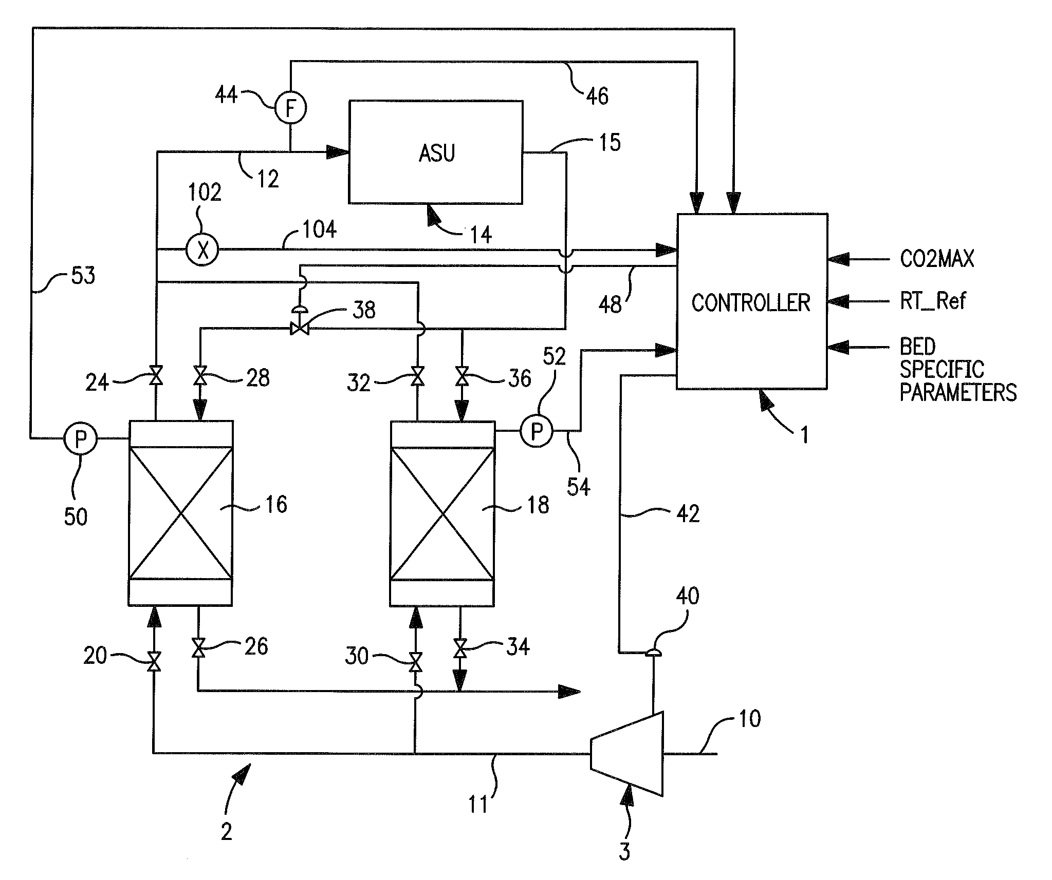
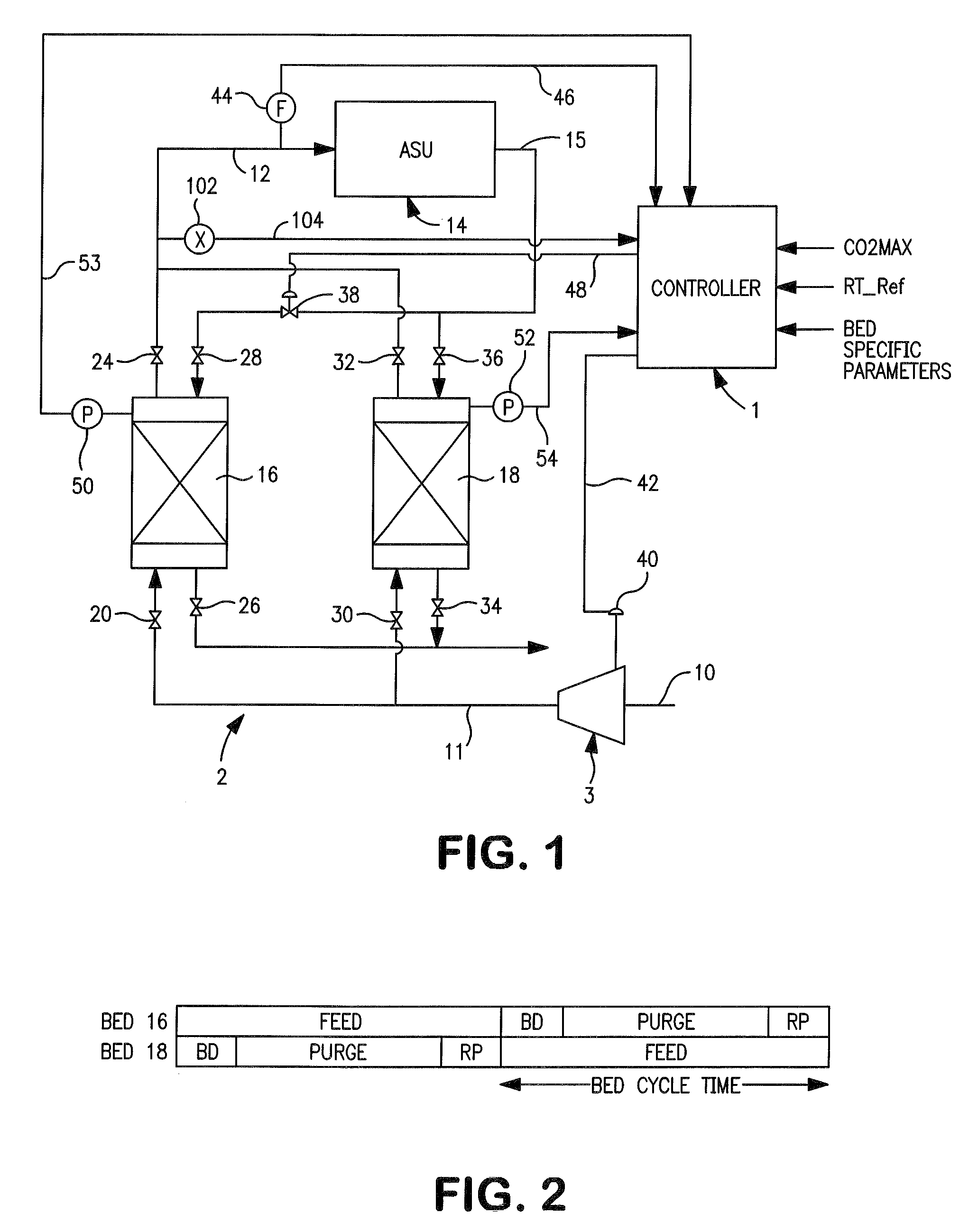
[0028]With reference to FIG. 1 a controller 1 in accordance with the present invention is illustrated for use in connection with the control of a pressure swing adsorption unit 2 and its associated compressor 3. A feed stream 10 is compressed by compressor 3 to produce a compressed feed stream 11 that is fed into pressure swing adsorption unit 2 to produce a product stream 12 that is fed into an air separation unit cold box 14 (“ASU”) as the main feed air.

[0029]It is understood that the use of the present invention in connection with air separation cold box 14 is for purposes of illustration only and is not intended to be limiting. This being said, as would be known by those skilled in the art, air separation unit cold box 14 would have one or more distillation columns for rectifying the air contained within feed stream 10 to produce a nitrogen product or possibly also, an oxygen product and an argon product. In this regard, the air separation unit cold box 14 is also provided with ...


PUM

PropertyMeasurementUnit
operational pressureaaaaaaaaaa
flow rateaaaaaaaaaa
feed flow rateaaaaaaaaaa

Abstract

A method for controlling an adsorption unit and associated compressor that adjusts the flow rate of a compressed feed stream produced by the compressor so that it increases from a nominal flow rate and then decreased back to the nominal flow rate. The increase and decrease of the feed stream flow rate are controlled in accordance with increase and decrease rate functions of adsorbent bed pressure ratio between off-line and on-line adsorbent beds and a triggering pressure ratio at which the feed flow rate decreases. Each of the increase and decrease rate functions is tuned to produce a similar response in the flow of a product stream produced by the adsorption unit. Additionally, repressurization time is controlled by driving it toward a target value that allows the purge stage of regeneration to be maximized and therefore, the degree to which each of the adsorbent beds is regenerated.

Description

FIELD OF THE INVENTION[0001]The present invention relates to a method of controlling repressurization of an adsorbent bed of an adsorption unit in which the regeneration of the adsorbent beds during the repressurization is optimized by controlling the feed flow rate of a compressed feed stream that is compressed within a compressor such that fluctuations within the flow rate of the product streams are minimized and similar for each of the adsorbent beds and repressurization is controlled to drive repressurization times for the adsorbent beds toward a target repressurization time.BACKGROUND OF THE INVENTION[0002]Adsorbent units are utilized to adsorb one or more components that are contained in a feed stream to produce a product stream. The adsorption is carried out in adsorbent beds that are operated in and out of phase cycle such that while one bed is on-line and adsorbing component or components of the feed stream, another off-line bed is being regenerated. There are a variety of ...

Claims


Application Information

Patent Timeline
Patent Type & Authority Patents(United States)
IPC IPC(8): B01D53/04G05B13/00
CPCB01D53/047G05B13/024B01D53/0462B01D53/0476B01D53/261B01D2256/10B01D2256/12B01D2256/18B01D2257/502B01D2257/504B01D2257/80B01D2259/40007B01D2259/40052B01D2259/402Y02C10/08F25J3/04181F25J3/04775F25J3/04781F25J2205/72F25J2230/40Y02C20/40
Inventor BLOUIN, STEPHANE
Owner PRAXAIR TECH INC
Why Eureka
Try Eureka