Method of correcting mask pattern

a mask pattern and mask technology, applied in the field of mask pattern correction, can solve problems such as deteriorating work efficiency, and achieve the effect of improving work efficiency and reducing processing tim

Inactive Publication Date: 2008-12-02
LAPIS SEMICON CO LTD
View PDF7 Cites 8 Cited by
  • Summary
  • Abstract
  • Description
  • Claims
  • Application Information

AI Technical Summary

Benefits of technology

[0017]Therefore, the objective of this invention is to provide a method for obtaining a desired mask pattern without deteriorating the work efficiency.
[0022]In the mask pattern correcting method of this invention, a close point and an isolated point between the defined pattern edge and the pattern edge of the design pattern are first determined, and then very small amount of correction is made to each edge of the mask pattern which is located within specified distance from the isolated point. Then, edges to be corrected which has small variation of close point light intensity and has large variation of isolated point light intensity at the mask pattern side are selected, and correction is repeatedly made to those selected edges so as to satisfy a specified criterion for correction. Once the pattern edge to be corrected, which is newly defined based on the after-correction mask pattern, and the edge of the design pattern satisfy the specified criterion for determining completion of correction, correction of the mask pattern is ended, so that effects of the light intensity of pattern edge which does not require correction is suppressed. The mask pattern edge that has larger deviation from the pattern edge of the design pattern is selectively corrected. Therefore, two-dimensional light intensity distribution does not have to be frequently determined in the whole mask pattern area, and therefore the processing time can be reduced and the work efficiency can be improved.

Problems solved by technology

Thus, if many calculations of the two-dimensional light intensity distribution are required, it will take more time to correct the mask pattern, which deteriorates the work efficiency.

Method used


Image

  • Method of correcting mask pattern
  • Method of correcting mask pattern
  • Method of correcting mask pattern

Examples


first embodiment

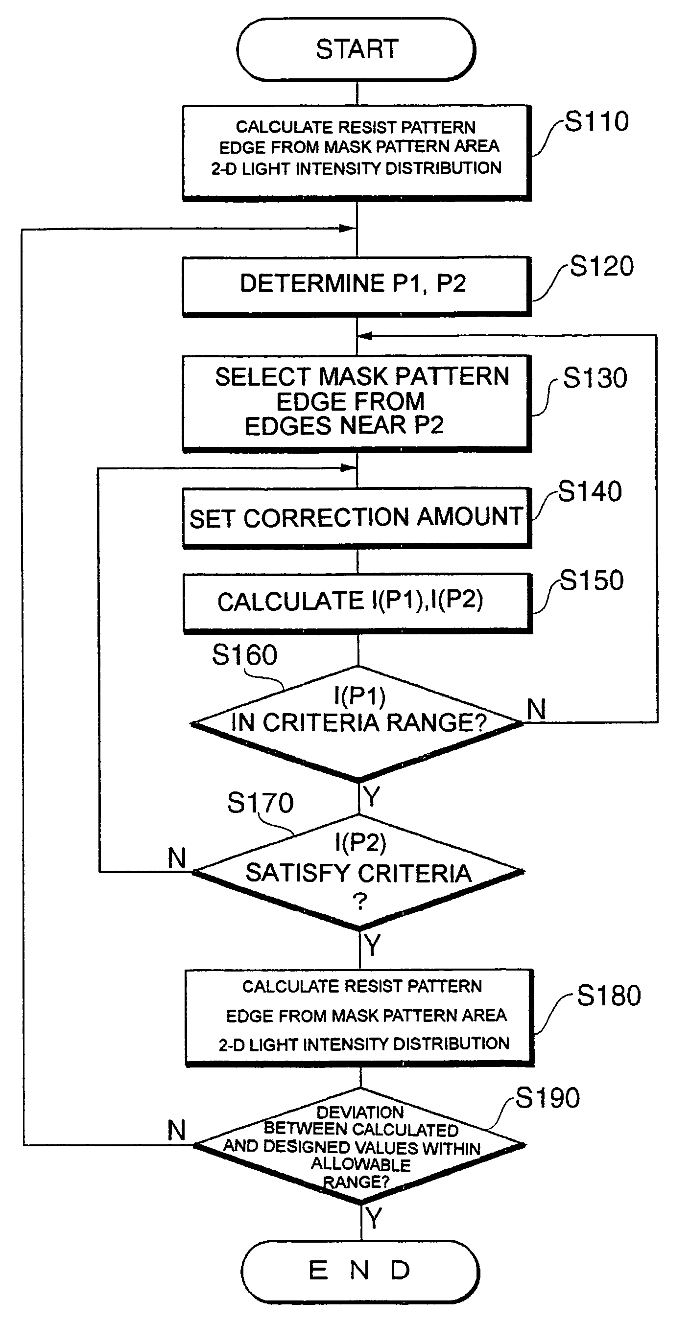
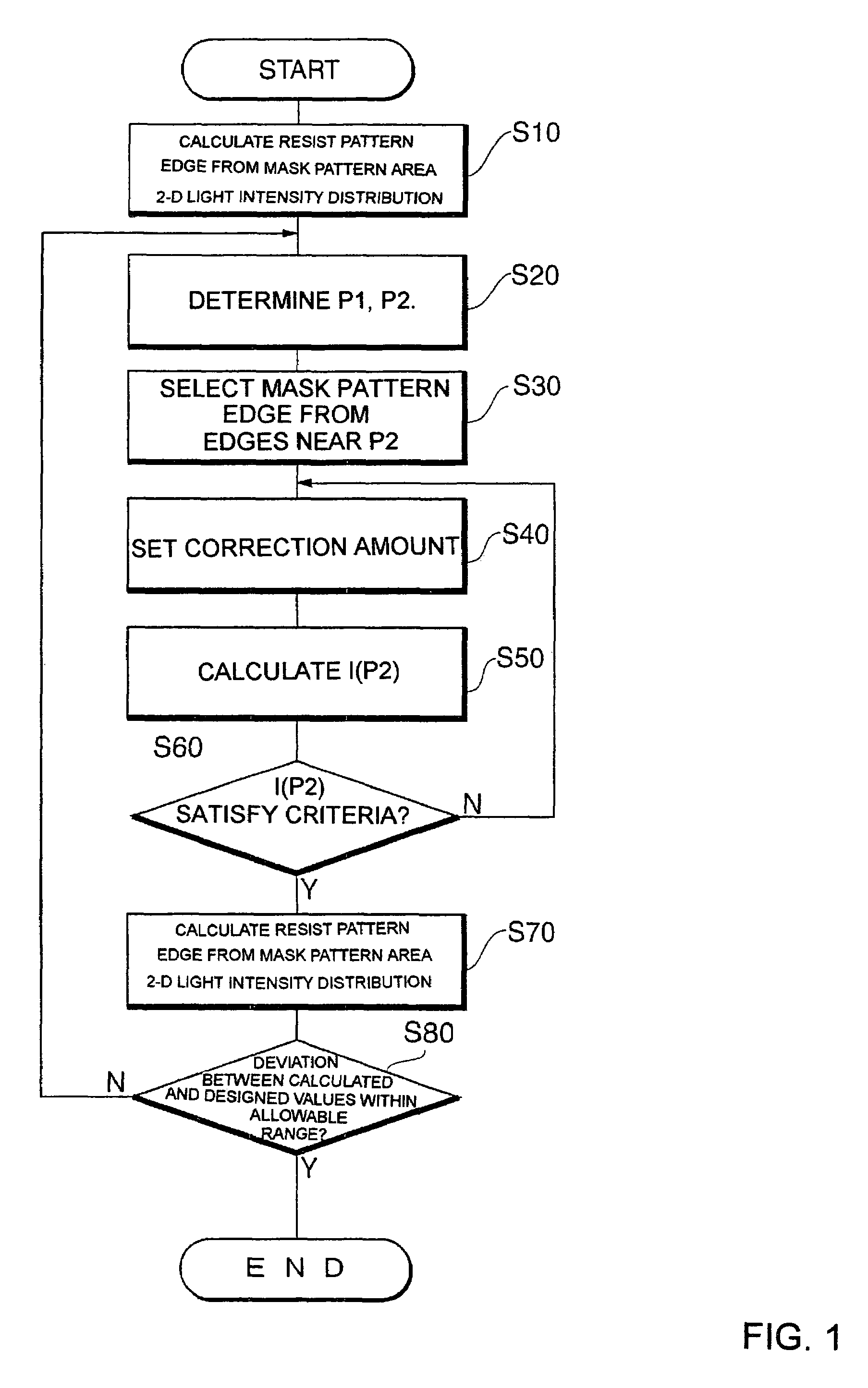
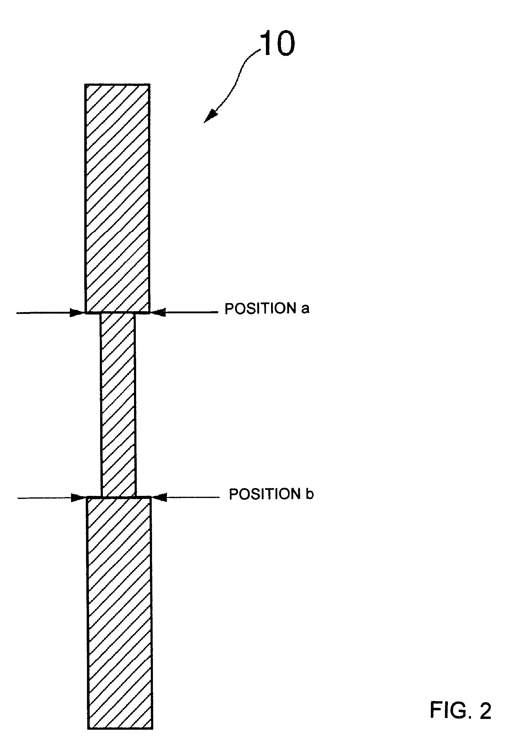
[0030]The mask pattern correcting method of this invention is a method to make corrections to the mask pattern is advance so as to make the resist pattern which is transferred to a resist (shown in FIG. 5) similar to the design pattern by performing patterning using mask patterns such as the phase-shifting mask FIG. 3) and Cr trim mask (FIG. 4) to transfer the design pattern of FIG. 2 to a resist. More specifically, the method of this invention is comprised of a before-correction pattern edge defining edge, a deviated position setting process, an edge selecting process, a correcting process, an after-correction pattern edge defining process and an end determining process. Each process is described below, referring to the flowchart of FIG. 1. In the before-correction pattern edge defining process, simulation is first performed using a mask pattern to be corrected. Then, two-dimensional light intensity distribution in the whole resist pattern area obtained by the simulation is determi...


PUM

PropertyMeasurementUnit
two-dimensional light intensity distributionaaaaaaaaaa
light intensitiesaaaaaaaaaa
light intensityaaaaaaaaaa

Abstract

A mask pattern correcting method is comprised of a before-correction pattern edge defining step for defining an edge of a mask pattern, a deviated position setting step for setting a close point and a isolated point based on the deviation between the pattern edges of the mask pattern and the design pattern, an edge selecting step for correcting an edge located within specified distance from the isolated point, and selecting a mask pattern edge that will have smaller variation of the close point light intensity and larger variation of isolated point light intensity by the correction, a correcting step for correcting an edge to be corrected such that the isolated point light intensity after correction satisfies a criterion for correction, an after-correction pattern edge defining step for defining a pattern edge of the corrected mask pattern, and an end determining step for ending correction when the deviation between the defined after-correction pattern edge and the edge of the design pattern is within a specified criteria for determining ending correction.

Description

BACKGROUND OF THE INVENTION[0001]1. Field of the Invention[0002]The present invention relates to a method of correcting a mask pattern for obtaining a desired photoresist pattern that corresponds to a design pattern by optical lithography with a mask pattern.[0003]2. Description of the Related Art[0004]Making a semiconductor device includes a lithography process. The lithography process is a process to pattern a resist using a projection optical system type exposure system. The exposure system for patterning is equipped with a mask pattern called “reticle”, and performs patterning on a resist with an image formed by transmission of light irradiated to the mask pattern.[0005]When patterning is performed by the above-described exposure system with the mask pattern, and if the exposure system is used at the edge of its capability, the pattern shape obtained by the exposure becomes different from that of the design pattern.[0006]To solve this problem, so-called “Optical proximity Correc...

Claims


Application Information

Patent Timeline
Patent Type & Authority Patents(United States)
IPC IPC(8): G03F1/00G03C3/02G03C5/00G03F1/36G03F1/68G03F1/70G03F9/00G06F17/50
CPCG03F1/144G03F1/36
Inventor SASAKI, SUGURU
Owner LAPIS SEMICON CO LTD
Why Eureka
Try Eureka