Backing plate unit for a rotary grinding machine

a backing plate and rotary grinding technology, which is applied in the direction of grinding machines, grinding/polishing apparatuses, abrasion apparatus, etc., can solve the problems of inability to accurately grind, inability to see the grinding result, and inability to suction the machine, so as to achieve the effect of improving the grinding result and reducing the pressur

Active Publication Date: 2015-09-15
JOST GMBH & CO KG
View PDF28 Cites 0 Cited by
  • Summary
  • Abstract
  • Description
  • Claims
  • Application Information

AI Technical Summary

Benefits of technology

[0014]Since the suction hood is arranged at the back face of the backing plate, a dust suctioning can be carried out through the backing plate and via the suction hood. Thus, the dust is sucked off directly at the grinding surface and has not to be centrifuged from the grinding disc outwards in order to be sucked off outside the grinding disc by means of a protruding hood. Thus on the one hand the dust suctioning is improved and on the other hand the life time of the grinding discs is increased since they clog less fast. Furthermore, the advantage results that the border of the grinding disc is always visible and thus an accurate grinding becomes possible.
[0020]Preferably, the suction hood comprises at its border facing the backing plate a brush rim or a slip ring. The brush rim or the slip ring allows a rotation of the backing plate with respect to a still-standing suction hood and ensures simultaneously a good sealing between these two parts in order to use the generated low pressure in the suction hood possibly completely for the dust suctioning through the grinding disc.
[0022]Preferably, the drive shaft comprises a rubber member. This rubber member compensates a canting of the backing plate and ensures that the backing plate always lies even on the work piece if desired and thus no grooves are affected.
[0023]Preferably, the suction hood comprises bellows at its barrel. The bellows compensate slight differences in the angle between suction hood and the backing plate and ensure a good sealing of these parts.
[0030]Preferably, the border of the backing plate is broadened to become a barrel face. Also this allows a qualitatively optimum and fast grinding of an edge or concave fillet of a work piece, wherein an exact radius of the concave fillet can be realized. This is likewise not possible with eccentric grinders.

Problems solved by technology

But this is because of the missing suction, neither optimum for the health of the user nor for the environment, since these coatings are declared to be toxic and the grinding dust comes into the environment during grinding.
But such suction hoods are only machine-specific and are only offered for some few rotary grinding machines.
The suction hood is for every machine fixed rigidly to the machine housing and is due to the system significantly larger than the backing plate and the grinding disc so that the grinding result cannot be seen during the grinding process and an accurate grinding is not possible.
But then in this area no suctioning is carried out anymore so that for such machines inspite of the suctioning very much grinding dust is released.
According to this, such a suction hood comprises a more or less large distance to the work piece and the brush rim is not able to sufficiently seal at the work piece anymore.
Also this leads to a worse suctioning and an increased dust contamination.

Method used


Image

  • Backing plate unit for a rotary grinding machine
  • Backing plate unit for a rotary grinding machine
  • Backing plate unit for a rotary grinding machine

Examples


Embodiment Construction

[0051]In the following, preferred embodiments of the present invention are described by means of the accompanying figures. Features of single embodiments can be also combined with other embodiments.

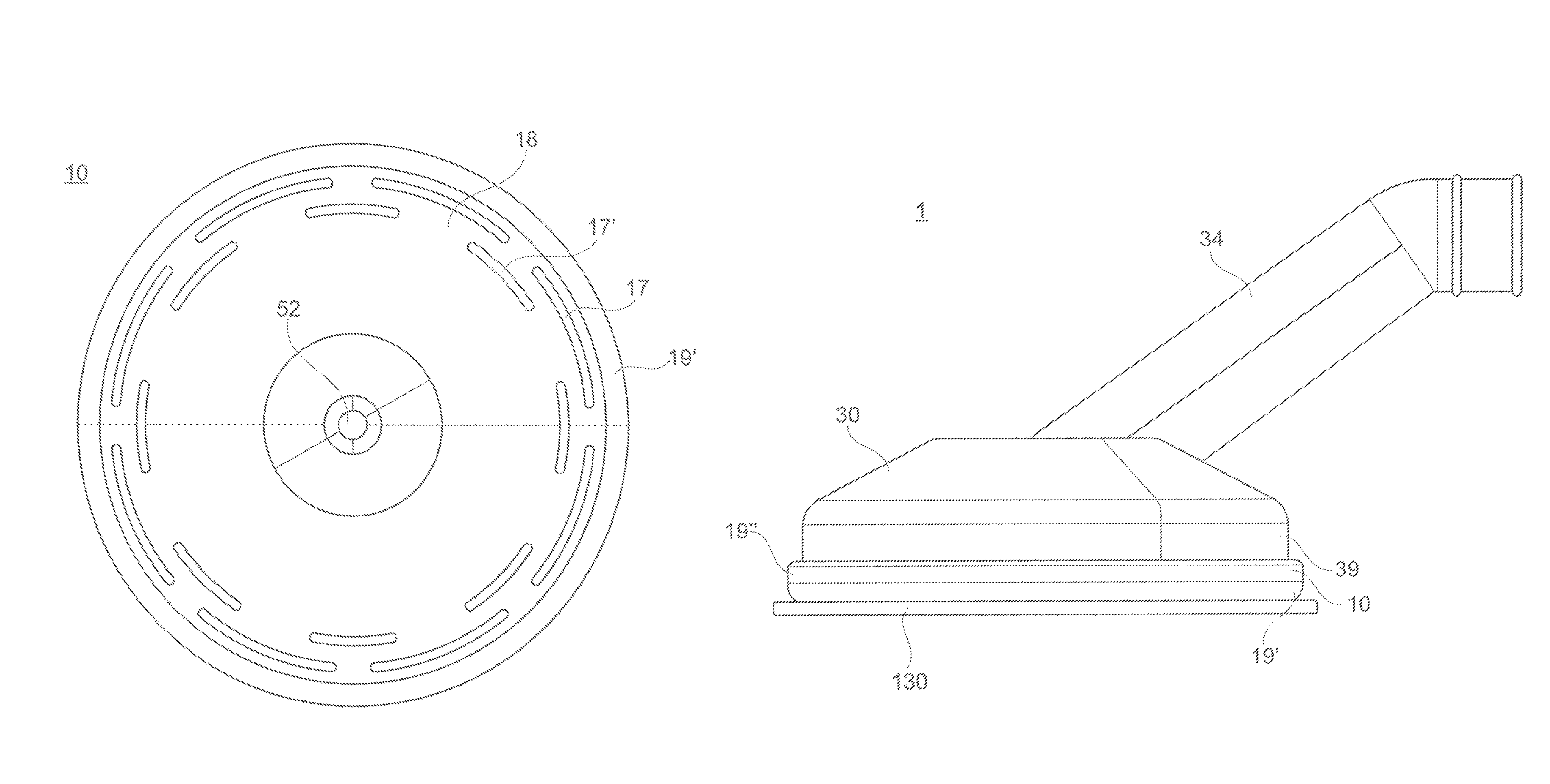
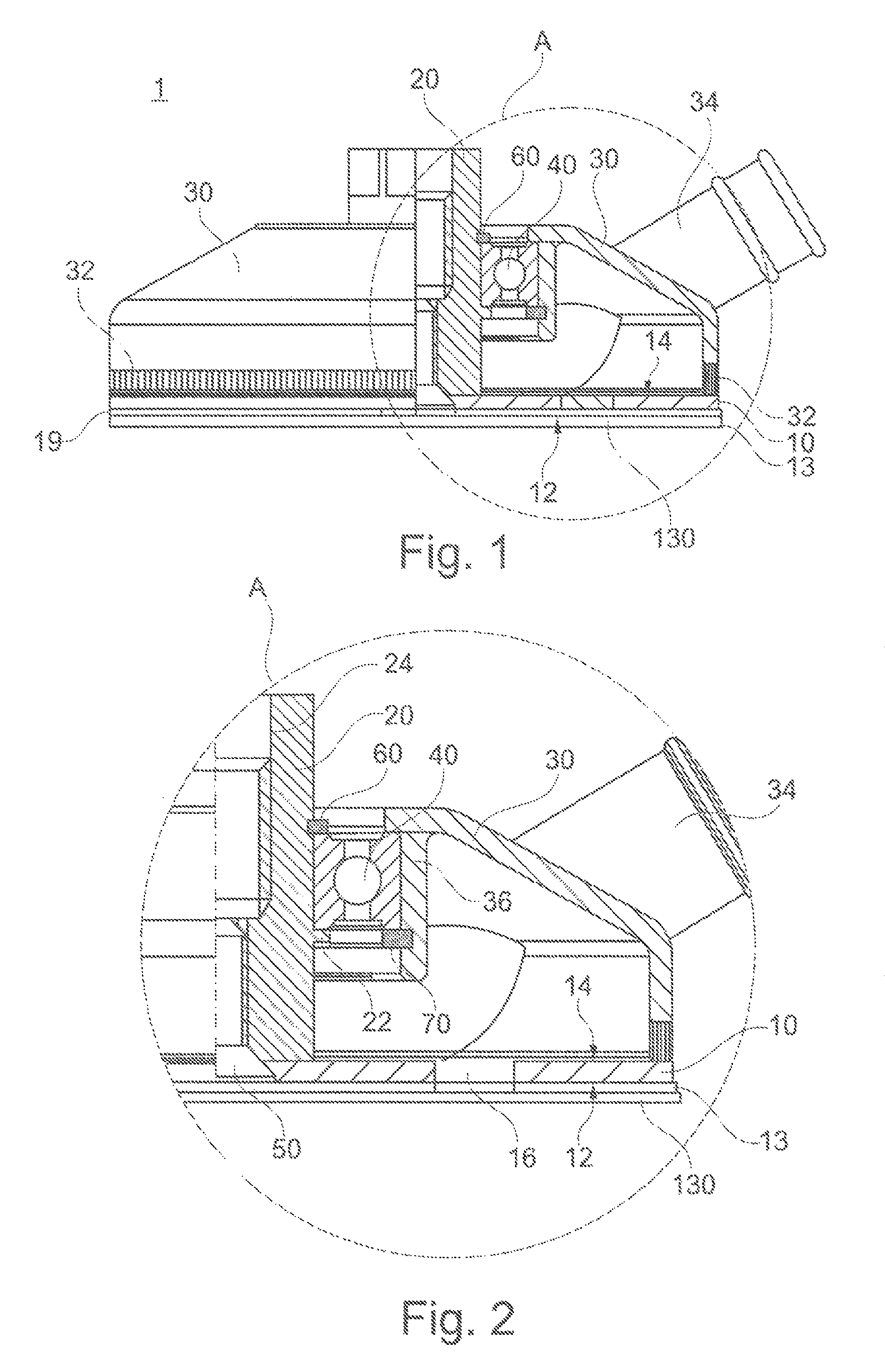
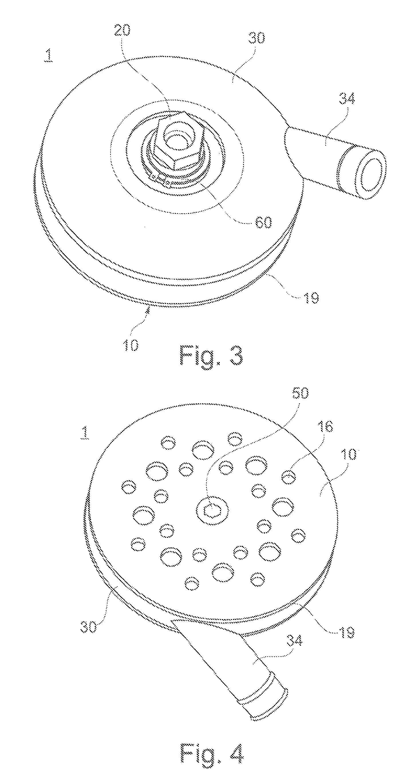
[0052]FIGS. 1 to 5 show a first preferred embodiment of a backing plate unit 1 for a rotary grinding machine 100. As shown in FIG. 1 in a partial section view and FIG. 2 in detail, the backing plate unit 1 comprises a drive shaft 20, at which by means of a screw 50 a backing plate 10 is rigidly connected. A suction hood 30 is rotatably mounted at the drive shaft 20 via a ball bearing 40. Thus, it is possible to suck off dust by means of the suction hood 30 through the backing plate 10 by means of a suction pipe 120 that is connected to a suction socket 34.

[0053]As it can be seen in particular in FIG. 2, the suction hood 30 is only rotatably fixed to the drive shaft 20. To this end, a ball bearing 40 is inserted in a cylindrical seat 36 of the suction hood 30 wherein the ball bearing 40 is...


PUM


Abstract

A backing plate unit for a rotary grinding machine includes a backing plate with a front face for mounting a grinding disc and a back face opposite the front face, a drive shaft that can be attached to the tool adaptor of the rotary grinding machine, and a suction hood that is rotatably fixed to the drive shaft. The backing plate 10 includes suction openings that penetrate the backing plate so that the suction hood 30 vacuums dust through the backing plate to the back face of the backing plate.

Description

1. FIELD OF THE INVENTION[0001]The present invention relates to a backing plate unit for a rotary grinding machine like it is used for the manufacturing of fine surfaces, like for instance in the automotive-, furniture-, painting- and polymer-fields.2. PRIOR ART[0002]For the manufacturing of super-finished surfaces in general hand grinding machines are used, like for instance eccentric-, delta- and swing-grinders. One of the main reasons therefore is, that these grinding machines are provided with suction devices that allow sucking grinding dust off, that is generated during grinding. That increases the grinding power of the grinding means and results in addition in a better grinding result. But since the oscillating grinding movement, the grinding volumes during grinding with these machines are significantly smaller than with rotatory grinding machines, wherein the grinding means rotates continuously in one direction. For grinding tasks, wherein a higher grinding power is desired a...

Claims


Application Information

Patent Timeline
Patent Type & Authority Patents(United States)
IPC IPC(8): B24B55/10B24D9/08B24B9/10B24B41/047
CPCB24B55/102B24B9/10B24B41/047B24D9/08
Inventor JOST, PETER
Owner JOST GMBH & CO KG
Why Eureka
Try Eureka