
Flap edge noise reduction fins

a technology of flap edge and noise reduction fin, which is applied in the direction of wing lift eficiency, airflow influencer, fuselage insulation, etc., can solve the problems of increasing airport noise restrictions, airframe noise, and airframe noise, so as to reduce noise, reduce steady pressure differential, and reduce local hydrodynamic fluctuations.

Active Publication Date: 2015-09-15
NASA
View PDF35 Cites 20 Cited by
  • Summary
  • Abstract
  • Description
  • Claims
  • Application Information

AI Technical Summary

Benefits of technology

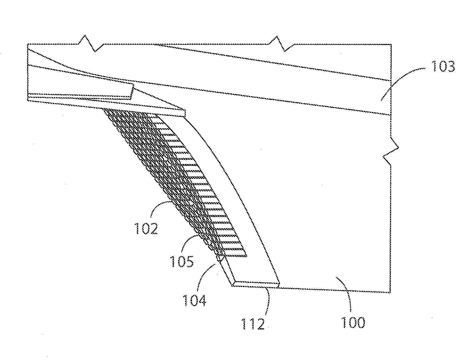
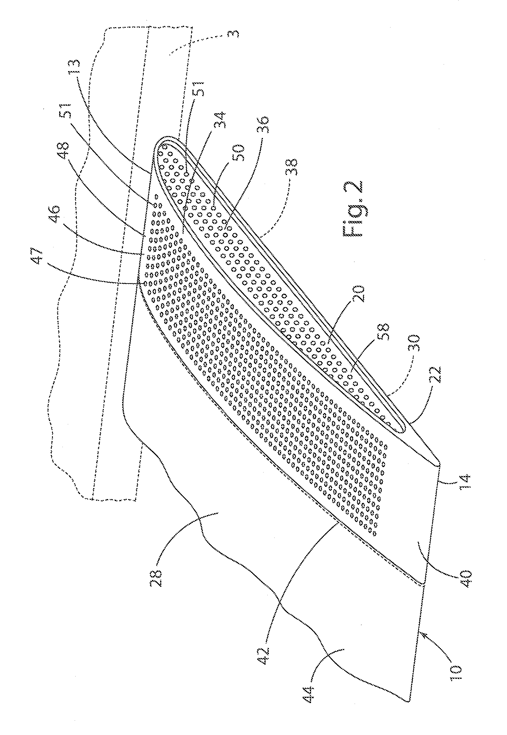
The present invention relates to a method for reducing noise generated by an aircraft's wing flap during approach and landing. The method involves adding several rigid protrusions to the side edge of the wing flap. These protrusions help to decrease the steady pressure difference that the wing flap is subjected to during use. Additionally, the protrusions also decrease the strength of local hydrodynamic fluctuations that occur when there is unsteady flow over the wing flap. This results in lower levels of noise generated during aircraft operation.

Problems solved by technology

One of the more important constraints to the continued growth of air traffic is the related concern regarding aircraft noise.
This concern has resulted in increasingly stringent noise restrictions for airports.
During aircraft take-off, the dominant aircraft noise source is generally the propulsion noise from the engines of the aircraft.
This airframe noise is caused by the interaction of the unsteady and typically turbulent airflow with the aircraft structures.
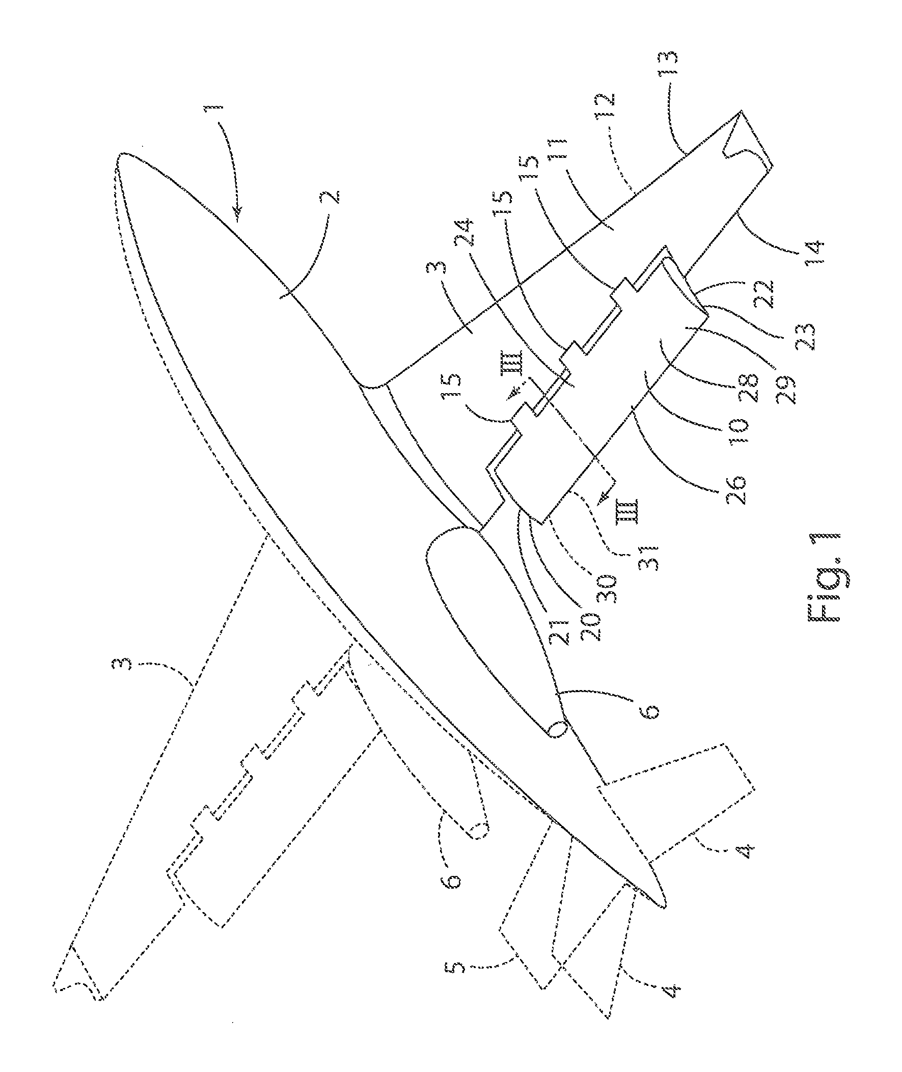
The sound radiated from the side edge of a partial-span flap is one of the major contributors to airframe noise during aircraft approach and landing.
Although use of brushes at flap and slat tips has generally been effective for reducing noise produced by these components, the use of brushes has negative side effects.
These side effects include degradation in aerodynamic performance of the high-lift wing during landing, and alteration of stall characteristics of the aircraft due to reduction in the maximum lift coefficient.

Method used


Image

  • Flap edge noise reduction fins
  • Flap edge noise reduction fins
  • Flap edge noise reduction fins

Examples


Embodiment Construction

[0026]For purposes of description herein, the terms “upper,”“lower,”“right,”“left,”“rear,”“front,”“vertical,”“horizontal,” and derivatives thereof shall be related to the invention as oriented in FIG. 1. However, it is to be understood that the invention may assume various alternative orientations, except where expressly specified to the contrary. It is also to be understood that the specific devices and processes illustrated in the attached drawing, and described in the following specification are simply exemplary embodiments of the inventive concepts defined in the appended claims. Furthermore, references to specific items or features (e.g. a wing structure, leading edge slat, and slat cove filler) shall not be construed as limiting the item or feature to one-piece or multi-piece items or features. Hence, specific dimensions and other physical characteristics relating to the embodiments disclosed herein are not to be considered as limiting, unless the claims expressly state otherw...


PUM


Abstract

A flap of the type that is movably connected to an aircraft wing to provide control of an aircraft in flight includes opposite ends, wherein at least a first opposite end includes a plurality of substantially rigid, laterally extending protrusions that are spaced apart to form a plurality of fluidly interconnected passageways. The passageways have openings adjacent to upper and lower sides of the flap, and the passageways include a plurality of bends such that high pressure fluid flows from a high pressure region to a low pressure region to provide a boundary condition that inhibits noise resulting from airflow around the end of the flap.

Description

CROSS-REFERENCE TO RELATED APPLICATION[0001]This application is a continuation-in-part of U.S. patent application Ser. No. 13 / 417,347 titled “Flap Side Edge Liners for Airframe Noise Reduction,” filed on Mar. 12, 2012, which claims priority to U.S. Provisional Application Nos. 61 / 451,727, titled “Flap Side Edge Liners for Airframe Noise Reduction,” filed on Mar. 11, 2011; 61 / 451,730, titled “Landing Gear Door Liners for Airframe Noise Reduction,” filed on Mar. 11, 2011; 61 / 451,735, titled “External Acoustic Liners for Multi-Functional Aircraft Noise Reduction,” filed on Mar. 11, 2011; and 61 / 597,282, titled “Reactive Orthotropic Lattice Diffuser (ROLD) for Reducing Aerodynamic Noise from Aircraft Flap Tips,” filed on Feb. 10, 2012; the entire contents of all of the foregoing incorporated by reference in this application. This application also claims priority to U.S. Provisional Application No. 61 / 721,058, titled “Flap Edge Noise Reduction Fins,” filed on Nov. 1, 2012, the entire con...

Claims


Application Information

Patent Timeline
IPC IPC(8): B64C21/00B64C1/40
CPCB64C1/40B64C9/18B64C21/10B64C23/005B64C2230/14B64C2230/22B64C2230/24Y02T50/10Y02T50/30
Inventor KHORRAMI, MEHDI R.CHOUDHAN, MEELAN M.
Owner NASA
Learn More