Compressible valve for a pressurized container

a compression valve and container technology, applied in the direction of transportation and packaging, mechanical equipment, packaging, etc., can solve the problems of limited recycling ability of plastic pressurized containers, plastic pressurized containers including such valves are typically non recyclable, etc., and achieve the effect of stabilizing the position of the valve stem

Active Publication Date: 2015-09-15
PROCTER & GAMBLE CO
View PDF26 Cites 80 Cited by
  • Summary
  • Abstract
  • Description
  • Claims
  • Application Information

AI Technical Summary

Benefits of technology

[0014]The valve stem primary flange can have a primary flange diameter and the valve cup can include a cylindrical portion having an internal diameter near the open top portion which is substantially equivalent to the primary flange diameter such that the valve stem primary flange is in sliding contacting relationship with the valve cup internal diameter. The contacting relationship stabilizes the position of the valve stem. In addition, the valve cup may also include an internal edge near the open top portion of the valve cup. The internal edge has a diameter that is less than the valve stem primary flange diameter to limit the vertical travel of the valve stem in the valve cup opening by interfacing with the top side of the primary flange.

Problems solved by technology

Plastic pressurized containers including such valves are typically non recyclable.
Thus, the ability to recycle plastic pressurized containers is often limited due to dispensing nozzle.

Method used


Image

  • Compressible valve for a pressurized container
  • Compressible valve for a pressurized container
  • Compressible valve for a pressurized container

Examples


Embodiment Construction

[0027]The compressible valve according to the present invention will be described with reference to the following figures which illustrate certain embodiments. It will be apparent to those skilled in the art that these embodiments do not represent the full scope of the invention which is broadly applicable in the form of variations and equivalents as may be embraced by the claims appended hereto. Furthermore, features described or illustrated as part of one embodiment may be used with another embodiment to yield still a further embodiment. It is intended that the scope of the claims extend to all such variations and equivalents.

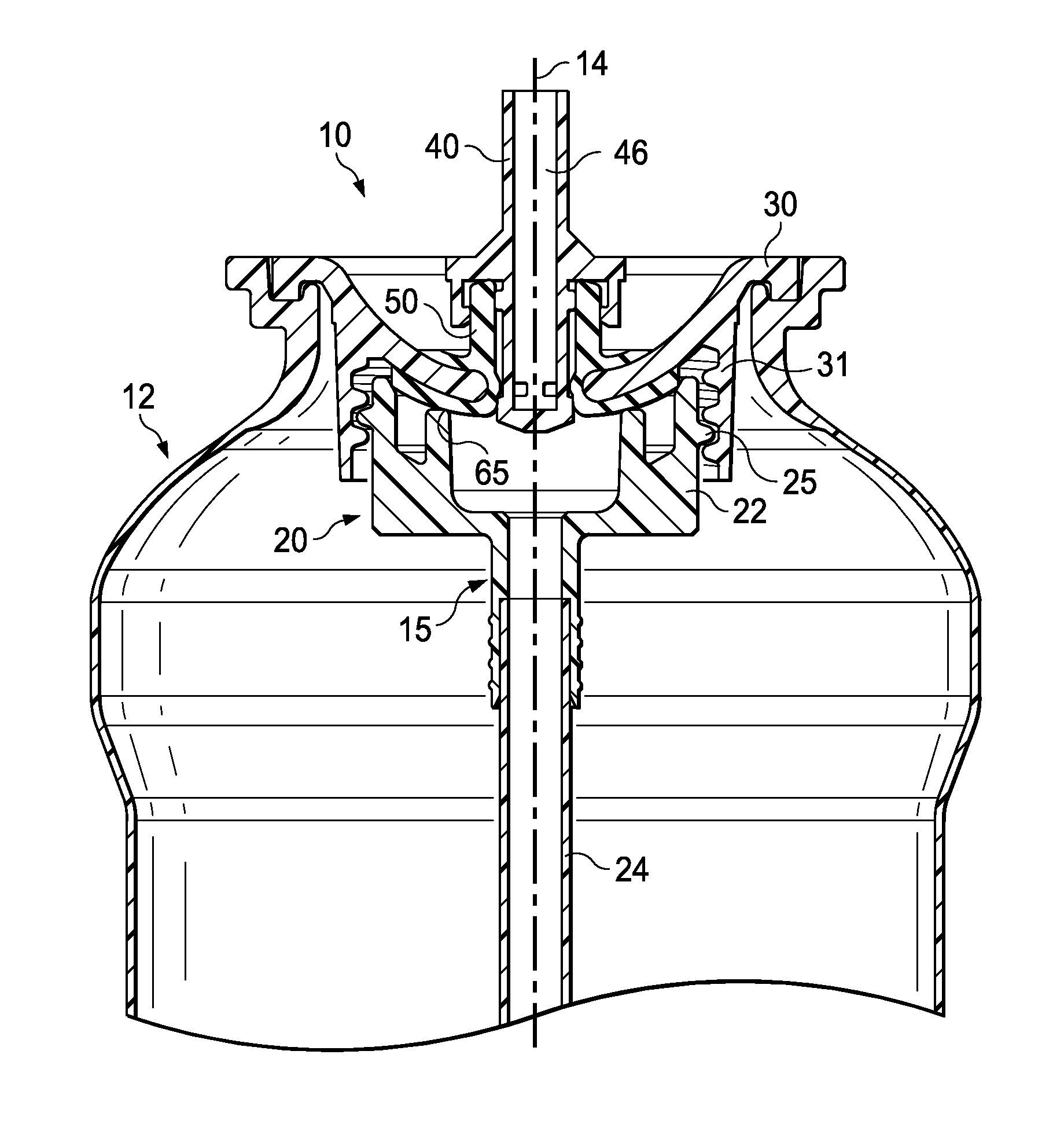
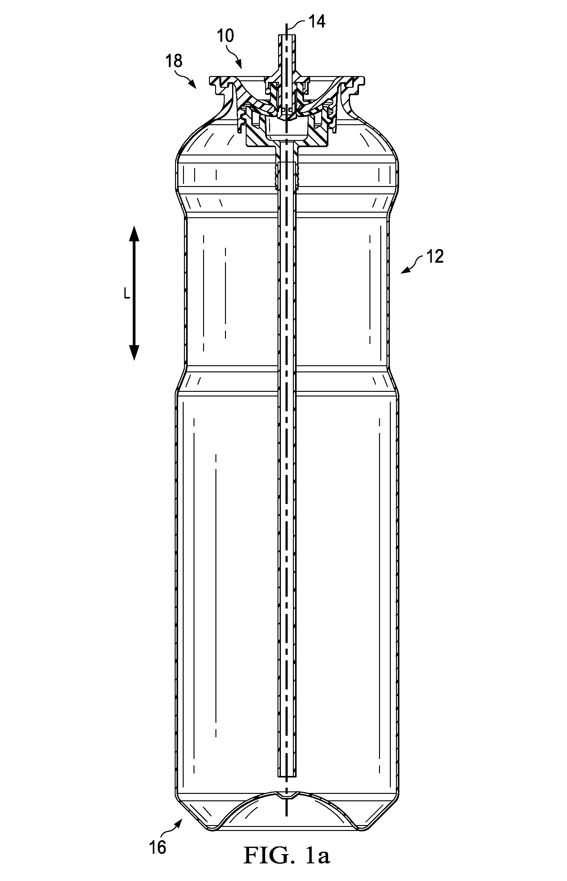
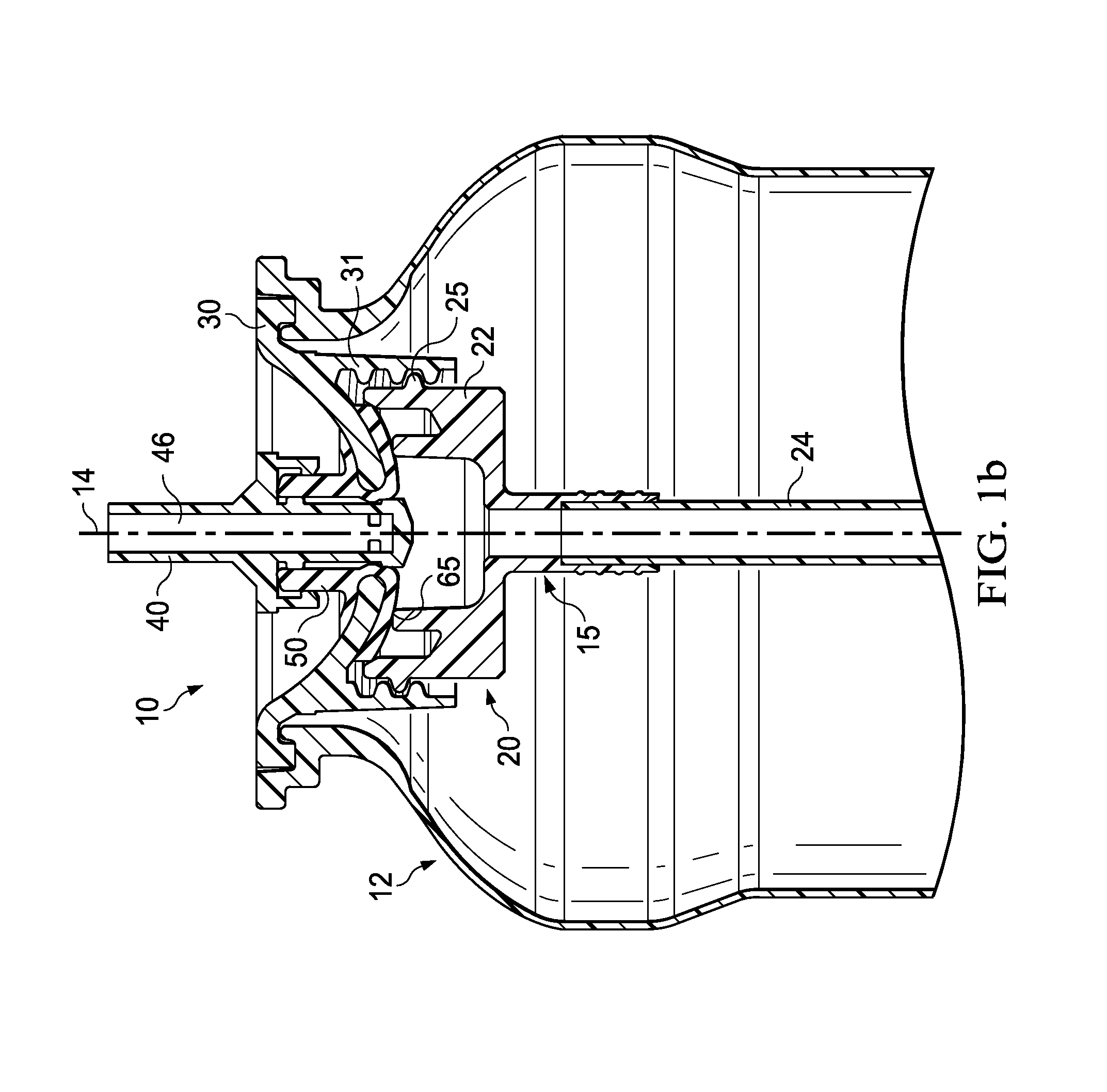
[0028]FIG. 1a is a schematic illustration of the valve assembly 10 and the container 12. Although not shown, a combined actuator and nozzle can be mounted on the valve assembly 10.

[0029]As shown in FIG. 1a, the container comprises a bottle 12 having a longitudinal axis 14 defining a longitudinal direction L and a dispensing structure 15. The bottle 12 has a c...


PUM


Abstract

A compressible valve is used with a pressurized container for dispensing an aerosol product. The compressible valve includes a valve cup connected to a dispensing structure disposed inside an open top end of a bottle. A grommet is disposed in the valve cup and has an integral sealing portion and spring portion. A grommet longitudinal passageway passes through the spring portion and the sealing portion and is coaxial with a valve cup longitudinal passageway. An elongate valve stem is disposed in the grommet passageway. The grommet sealing portion provides a seal between the valve stem and the valve cup and between the dispensing structure and the valve cup.

Description

FIELD OF THE INVENTION[0001]The present invention relates to a compressible valve for a pressurized container. Particularly, a compressible valve for use with a pressurized container for dispensing an aerosol product.BACKGROUND OF THE INVENTION[0002]The present invention relates to dispensers for aerosols or other pressurized products, and more particularly to a pressure resistant plastic bottle for dispensing an aerosol or other comparably pressurized product.[0003]The term “aerosol” will be understood herein to mean any non-refillable receptacle containing a gas compressed, liquefied or dissolved under pressure, the sole purpose of which is to expel a nonpoisonous (other than a Division 6.1 Packing Group III material) liquid, paste, or powder and fitted with a self-closing release device allowing the contents to be ejected by the gas. Aerosol products include but are not limited to foamed or gel preparations or to liquid products delivered in a non-aerosol stream.[0004]Pressurized...

Claims


Application Information

Patent Timeline
Patent Type & Authority Patents(United States)
IPC IPC(8): B65D83/00B65D83/48F16K1/34
CPCB65D83/48F16K1/34B65D83/38B65D83/46B65D83/62B65D83/64
Inventor SMITH, SCOTT EDWARDFRANCKHAUSER, ANDREW WILLIAM
Owner PROCTER & GAMBLE CO
Why Eureka
Try Eureka