Radiation imaging apparatus, method for controlling the same, and non-transitory computer-readable storage medium

a radiation imaging apparatus and computer-readable storage medium technology, applied in the direction of color television details, television system details, signal components lost, etc., can solve the problems of difficult to use a portable cassette-type radiation imaging apparatus for a long period of time, and the consumption of power by initializing operation, so as to improve the quality of radiation images

Active Publication Date: 2015-09-15
CANON KK
View PDF12 Cites 38 Cited by
  • Summary
  • Abstract
  • Description
  • Claims
  • Application Information

AI Technical Summary

Benefits of technology

[0007]The present invention provides a technique advantageous in improving the quality of a radiation image by properly performing radiation imaging.

Problems solved by technology

If, however, radiation is irradiated during the initializing operation, signal components are lost by the initializing operation during this period.
This leads to the consumption of power by the initializing operation even before the start of the radiation imaging.
This makes it difficult to use a portable cassette-type radiation imaging apparatus for a long period of time.

Method used


Image

  • Radiation imaging apparatus, method for controlling the same, and non-transitory computer-readable storage medium
  • Radiation imaging apparatus, method for controlling the same, and non-transitory computer-readable storage medium
  • Radiation imaging apparatus, method for controlling the same, and non-transitory computer-readable storage medium

Examples


first embodiment

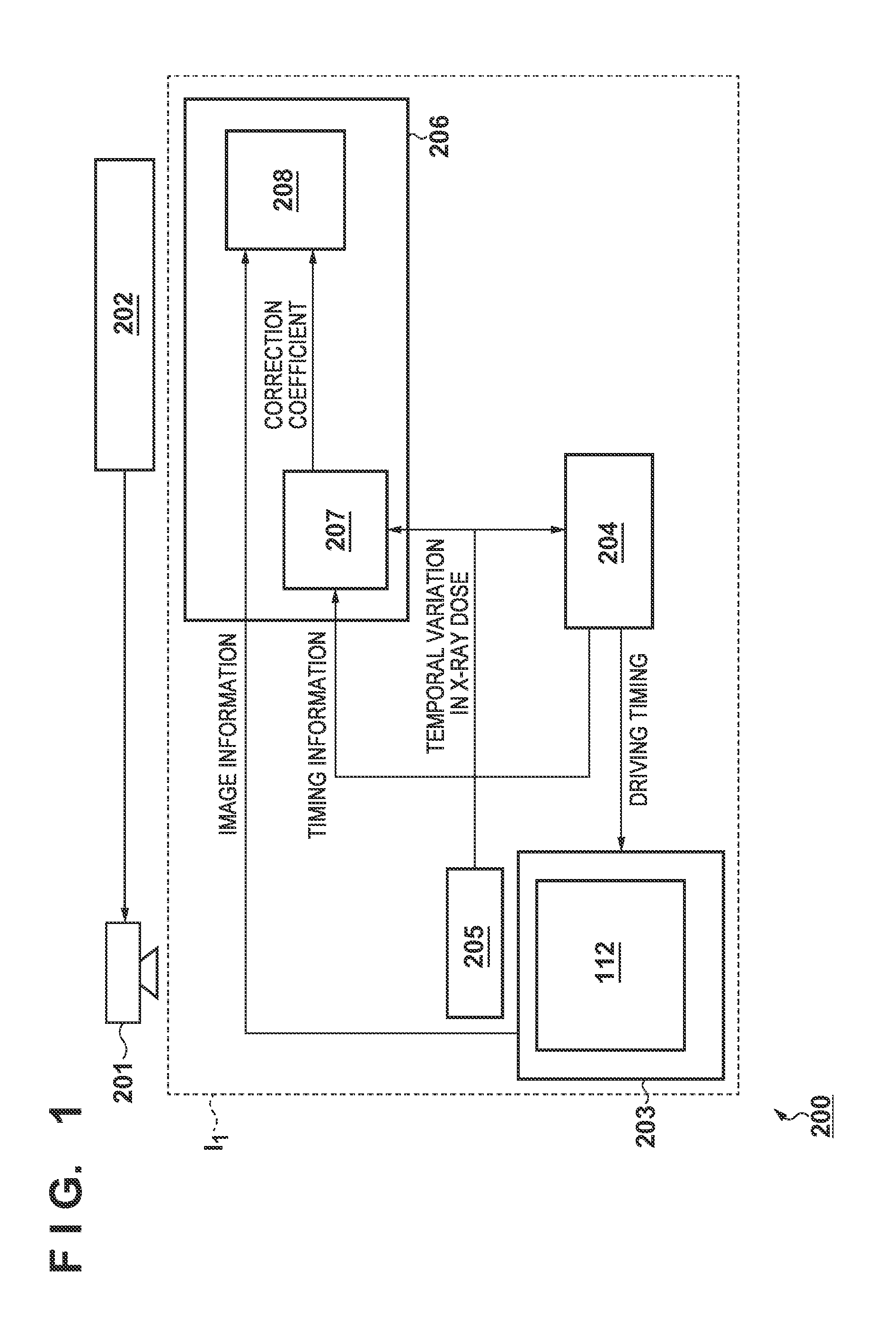
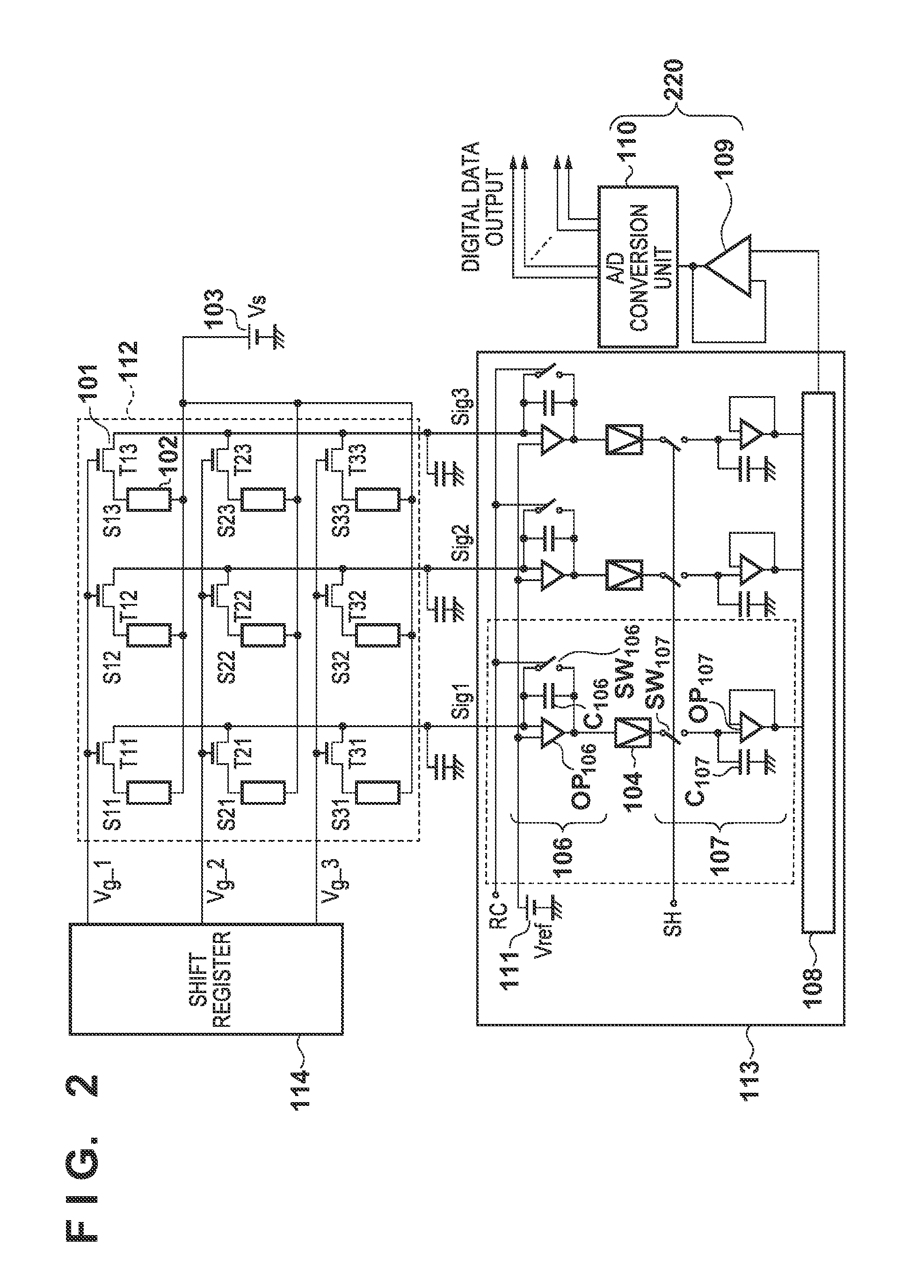
[0019]A radiation imaging apparatus I1 according to the first embodiment will be described with reference to FIGS. 1 to 4. FIG. 1 shows a radiation imaging system 200 including the radiation imaging apparatus I1. The radiation imaging system 200 includes a radiation source 201, a radiation controller 202, and the radiation imaging apparatus I1. The radiation source 201 generates radiation in response to an instruction from the radiation controller 202. Radiation includes particle rays and electromagnetic waves such as X-ray, α-rays, β-rays, γ-rays, and cosmic rays. The radiation imaging apparatus I1 includes a sensor panel 203 including a sensor array 112, a driving unit 204 for driving the sensor array 112, a detection unit 205 for detecting radiation, and a processing unit 206 for processing a signal from the sensor array 112. The sensor array 112 is configured such that, for example, a plurality of sensors (or pixels) form a plurality of rows and a plurality of columns, and outpu...

second embodiment

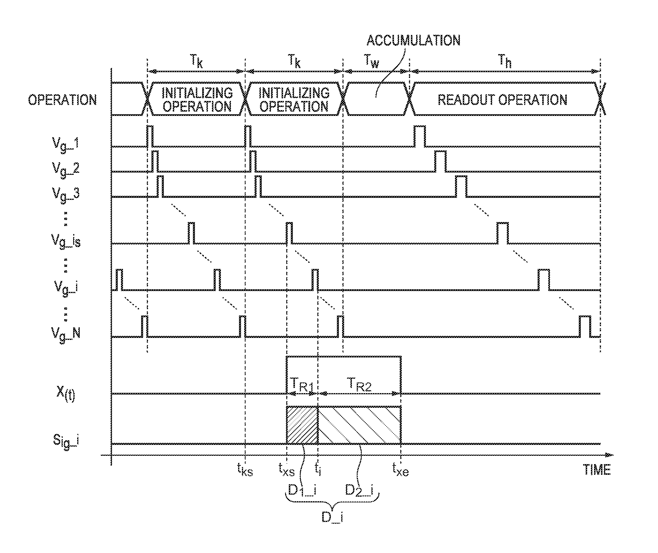
[0035]A radiation imaging apparatus I2 according to the second embodiment will be described with reference to FIG. 5. Like FIG. 4, FIG. 5 is a timing chart for radiation imaging in this embodiment. The embodiment differs from the first embodiment, which performs correction by using start time txs of the irradiation and end time txe, in that it performs the above correction from the measurement result on the radiation dose. A processing unit 206 calculates the ratio between a first radiation dose R1 measured in a first term TR1 and a second radiation dose R2 measured in a second term TR2 with respect to a sensor S on the ith row based on the measurement result on a radiation intensity X(t). The first term TR1 is the term from the start of the irradiation to the initialization, and the second term TR2 is the term from the end of the first term to the end of irradiation. The radiation doses R1 and R2 may be acquired by known calculation processing based on, for example, the output resu...

third embodiment

[0038]A radiation imaging apparatus I3 according to the third embodiment will be described with reference to FIGS. 6 and 7. The third embodiment differs from the second embodiment in that it ends initialization of sensors S of a sensor array 112 in accordance with the timing of the detection of radiation. FIG. 6 is a flowchart for radiation imaging in this embodiment. In S201, the apparatus repeatedly performs the initializing operation described in the first embodiment. The apparatus repeats the initializing operation until the process advances to S202, thereby periodically initializing the sensors S. In the embodiment, the apparatus interrupts initializing operation in accordance with the timing of the detection of the end of the irradiation by a detection unit 205. In S202, the apparatus performs readout operation in the same manner as in S102 in the first embodiment.

[0039]Like FIG. 4, FIG. 7 is a timing chart for radiation imaging in this embodiment. Consider a case in which the...


PUM


Abstract

A radiation imaging apparatus, comprising a sensor array in which a plurality of sensors configured to output signals corresponding to irradiated radiation, a detection unit configured to detect radiation, a driving unit configured to drive the sensor array, so as to initialize the plurality of sensors for each row repeatedly at least until the detection unit detects irradiation of radiation and to read out signals from the plurality of sensors for each row sequentially, and a processing unit configured to process signals from the sensor array, so as to correct a signal from the sensor on a row, of the plurality of sensors, which has been initialized during the irradiation of radiation, based on a timing of the initialization.

Description

BACKGROUND OF THE INVENTION[0001]1. Field of the Invention[0002]The present invention relates to a radiation imaging apparatus, a method for controlling the radiation imaging apparatus, and a non-transitory computer-readable storage medium.[0003]2. Description of the Related Art[0004]A radiation imaging apparatus performs an initializing operation that comprises periodically initializing each sensor of a sensor array and a readout operation that comprises reading out signals corresponding to the charges accumulated upon irradiation of radiation after the initializing operation. The apparatus performs the initializing operation to initialize charges due to the dark currents generated in the sensor array. If, however, radiation is irradiated during the initializing operation, signal components are lost by the initializing operation during this period.[0005]According to Japanese Patent Laid-Open No. 2002-181942, it is possible to perform correction by using the signals stored by the in...

Claims


Application Information

Patent Timeline
Patent Type & Authority Patents(United States)
IPC IPC(8): G01J1/42G01T1/16H04N5/32H04N5/361H04N5/357H04N5/374
CPCG01T1/16H04N5/32H04N5/3575H04N5/361H04N5/3742H04N25/616H04N25/63H04N25/767
Inventor IWASHITA, ATSUSHIKAMESHIMA, TOSHIOYAGI, TOMOYUKITAKENAKA, KATSUROSATO, SHOSUGAWARA, ERIKOOKADA, HIDEYUKI
Owner CANON KK
Why Eureka
Try Eureka