
Antenna structure and wireless communication device with the antenna structure

An antenna structure and radiation signal technology, which is applied in the direction of antenna grounding switch structure connection, antenna grounding device, and devices that enable antennas to work in different bands at the same time, can solve the problem of affecting the integrity and aesthetics of the backplane, easily interfering with signals, and not being able to Easy to solve problems such as broadband design, to achieve the effect of improving radiation quality, improving isolation, and lower mutual interference

Active Publication Date: 2022-05-06
SHENZHEN FUTAIHONG PRECISION IND CO LTD +1
View PDF5 Cites 0 Cited by
  • Summary
  • Abstract
  • Description
  • Claims
  • Application Information

AI Technical Summary

Problems solved by technology

However, the metal shell is easy to interfere with the signal radiated by the antenna installed in it, and it is not easy to achieve broadband design, resulting in poor radiation performance of the built-in antenna
Furthermore, slots and breakpoints are usually arranged on the backboard, which will affect the integrity and aesthetics of the backboard.

Method used


Image

  • Antenna structure and wireless communication device with the antenna structure
  • Antenna structure and wireless communication device with the antenna structure
  • Antenna structure and wireless communication device with the antenna structure

Examples


Embodiment Construction

[0061] The following will clearly and completely describe the technical solutions in the embodiments of the present invention with reference to the accompanying drawings in the embodiments of the present invention. Obviously, the described embodiments are only some, not all, embodiments of the present invention. Based on the embodiments of the present invention, all other embodiments obtained by persons of ordinary skill in the art without making creative efforts belong to the protection scope of the present invention.

[0062] It should be noted that when an element is referred to as being "electrically connected" to another element, it may be directly on the other element or there may be an intervening element. When an element is considered to be "electrically connected" to another element, it may be connected by contact, eg, by a wire connection, or non-contact, eg, by a non-contact coupling.

[0063] Unless otherwise defined, all technical and scientific terms used herein ...


PUM


Abstract

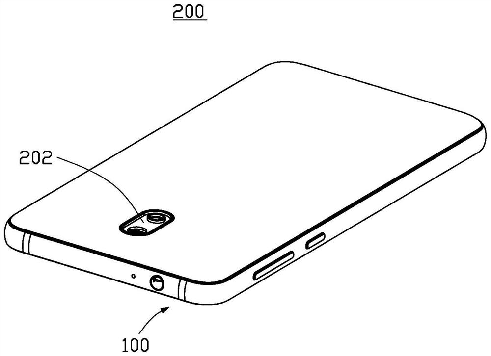
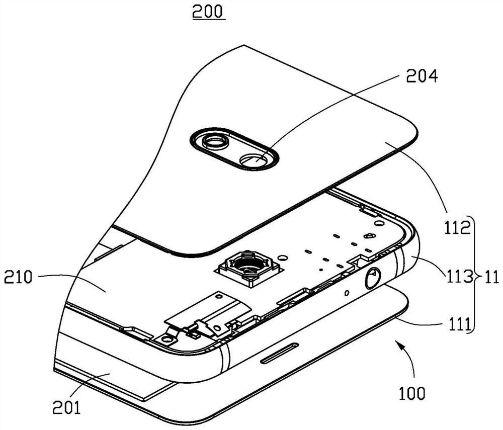
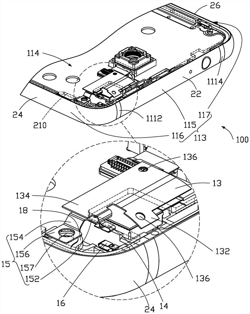
An antenna structure, comprising a radiating part, a grounding part, a feed-in part, a metal frame and a first matching circuit, the metal frame has a first breakpoint, and the first breakpoint forms a first breakpoint on one side of the metal frame. a radiating section, the radiating section is connected to the feed-in section and the grounding section and arranged at intervals inside the metal frame, and is electrically connected to the first radiating section, and one end of the first matching circuit is electrically connected to The first radiating section is close to one end of the first breakpoint, the other end of the first matching circuit is electrically connected to the ground part and connected to the ground, and the feeding part feeds current to the radiating part, the Both ends of the first radiation section and the first matching circuit are used to excite radiation signals in the first frequency band. Also provided is a wireless communication device with the antenna structure.

Description

technical field [0001] The invention relates to an antenna structure and a wireless communication device with the antenna structure. Background technique [0002] With the advancement of wireless communication technology, wireless communication devices are constantly developing towards a thinner and lighter trend, and consumers have higher and higher requirements for product appearance. Due to the advantages of metal casings in terms of appearance, structural strength, and heat dissipation effects, more and more manufacturers design wireless communication devices with metal casings, such as backplanes, to meet the needs of consumers. However, the metal shell easily interferes and shields the signal radiated by the antenna disposed therein, and it is not easy to achieve broadband design, resulting in poor radiation performance of the built-in antenna. Furthermore, the backplane is usually provided with slots and breakpoints, which will affect the integrity and aesthetics of ...

Claims


Application Information

Patent Timeline
Patent Type & Authority Patents(China)
IPC IPC(8): H01Q1/52H01Q1/44H01Q1/36H01Q1/48H01Q1/50H01Q1/22
CPCH01Q1/48H01Q9/42H01Q5/335H01Q1/243H01Q7/00H04M1/026H04M1/0283H01Q13/10H01Q5/35H01Q21/064H01Q9/0421
Inventor 李义杰林彦辉张云监林荣勤刘耿宏
Owner SHENZHEN FUTAIHONG PRECISION IND CO LTD
Learn More