
Medical valve with fluid volume alteration

a technology of fluid volume and medical valve, which is applied in the field of medical valves, can solve the problems of blood being drawn proximal into or toward the valve, compromising affecting the sterility of the valve,

Active Publication Date: 2015-09-22
NP MEDICAL
View PDF365 Cites 88 Cited by
  • Summary
  • Abstract
  • Description
  • Claims
  • Application Information

AI Technical Summary

Benefits of technology

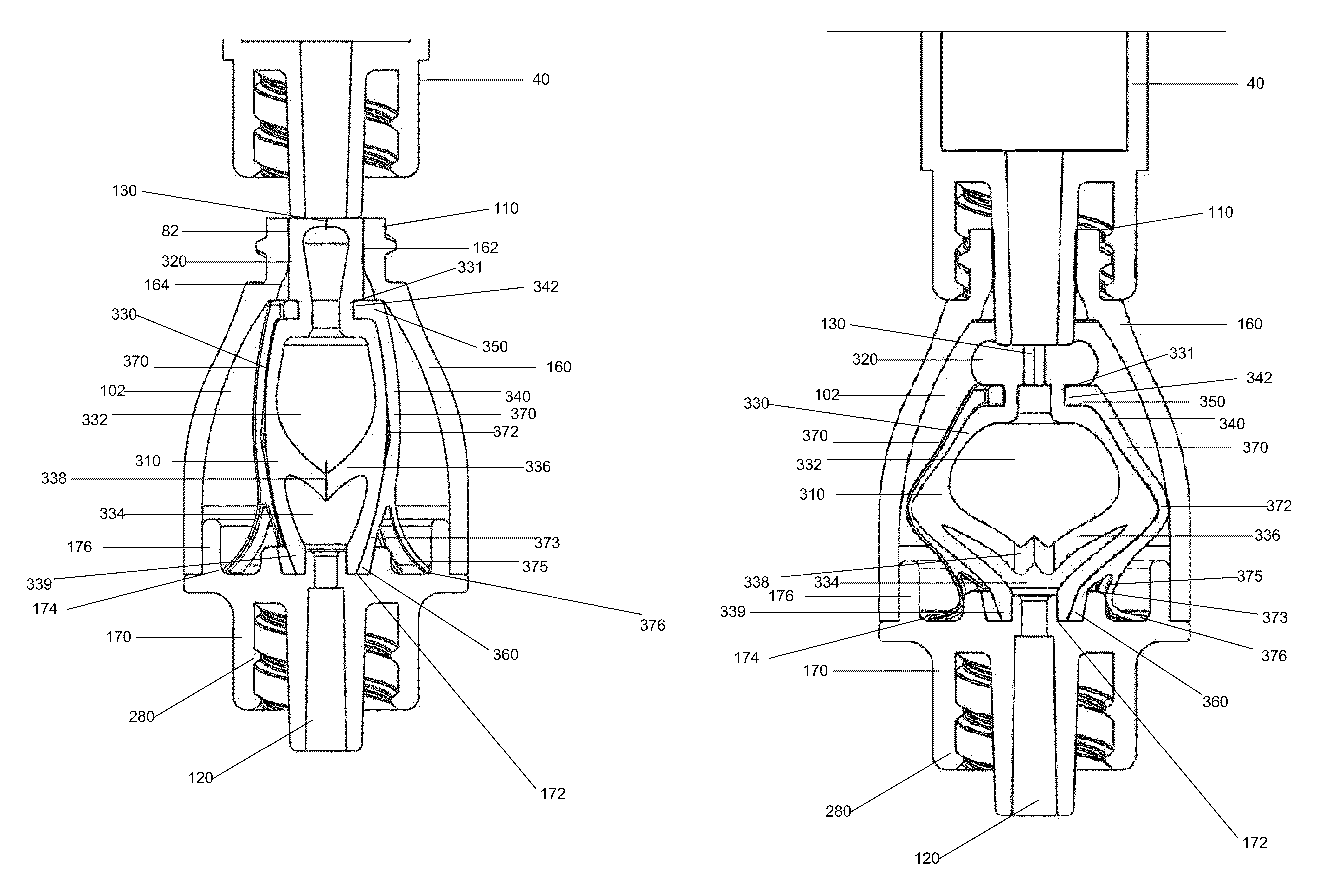
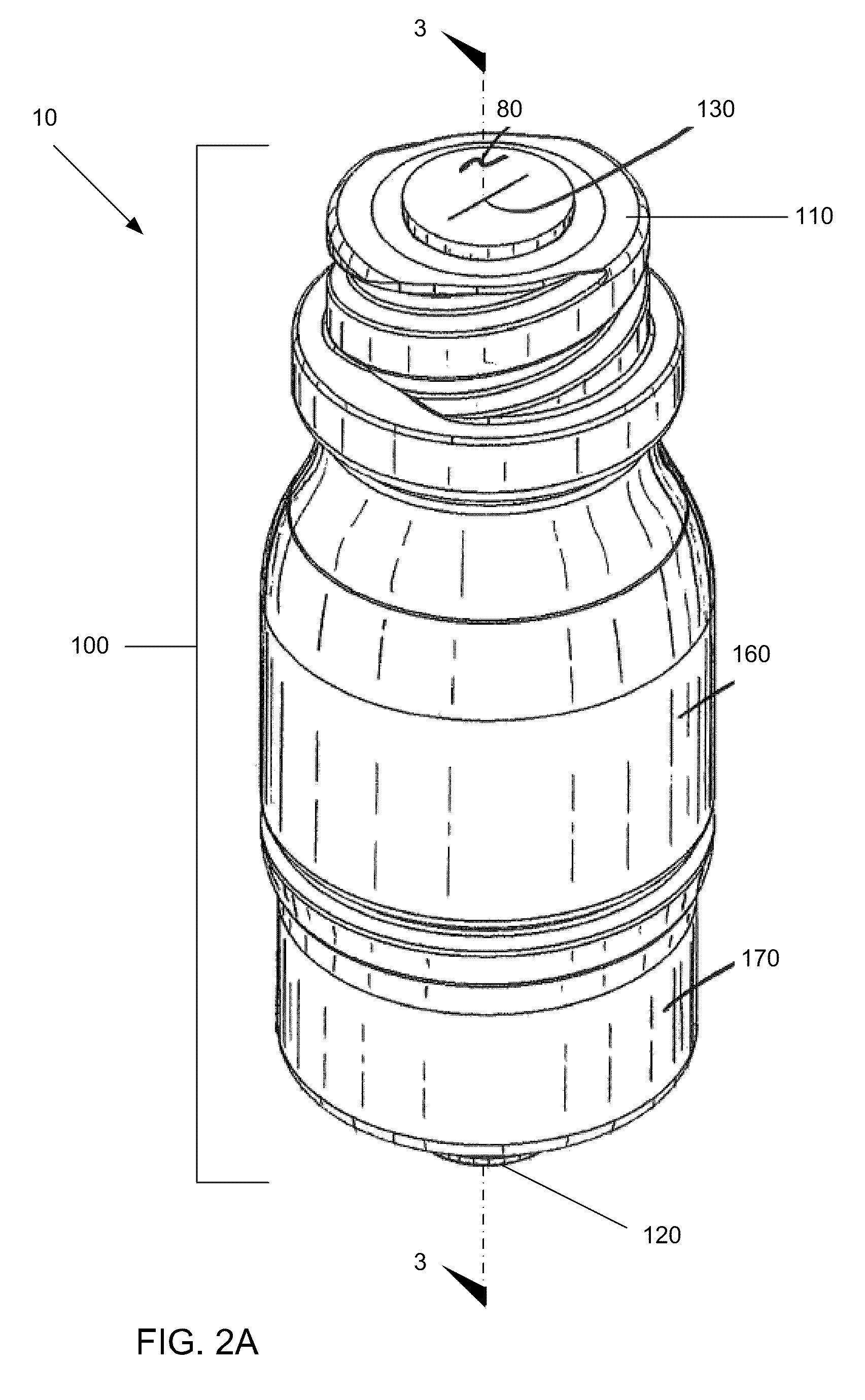
[0007]In accordance with additional embodiments, a medical valve may have an open mode that permits fluid flow, and a closed mode that prevents fluid flow. The medical valve may include a housing with an inlet and an outlet. The medical valve may also include a resilient member within the housing. The resilient member may have a proximal aperture and a distal aperture biased toward an open state to allow fluid flow through the valve when in the open mode. The resilient member may be deformed when the valve is in the closed mode to close distal aperture and prevent fluid flow through the valve. The distal aperture may return toward its open state as the valve transitions from the closed to open mode.
[0012]In accordance with additional embodiments, a method may include connecting a medical valve to a patient, inserting a medical implement through a valve inlet, moving the medical implement distally within the housing to transition the valve from a closed mode to an open mode, and transferring fluid between the medical implement and the patient through the valve. The medical valve may include a housing having the inlet and an outlet, a resilient member, and a control member. The resilient member may be within the housing and have a proximal aperture and a distal aperture biased toward an open state. The control member may deform the resilient member to close the distal aperture when the valve is in a closed mode. Distal movement of the medical implement may cause the control member to expand generally radially to allow the distal aperture to return toward the open state.

Problems solved by technology

Problems can arise, however, when the medical instrument is withdrawn from the valve.
Specifically, suction produced by the withdrawing medical instrument can undesirably cause blood to be drawn proximally into or toward the valve.
In addition to coagulating and impeding the mechanical operation of the valve, blood in the valve also compromises the sterility of the valve.

Method used


Image

  • Medical valve with fluid volume alteration
  • Medical valve with fluid volume alteration
  • Medical valve with fluid volume alteration

Examples


Embodiment Construction

[0026]In illustrative embodiments, a medical valve has an internal valve mechanism with a resilient member having a normally open distal aperture. The medical valve may also have a control member that compresses the resilient member to close the distal aperture when the valve is in the closed mode. Other embodiments of a medical valve have an internal resilient member with a normally outwardly biased body portion. Actuation of this valve urges the resilient member toward its free state. Details of illustrative embodiments are discussed below.

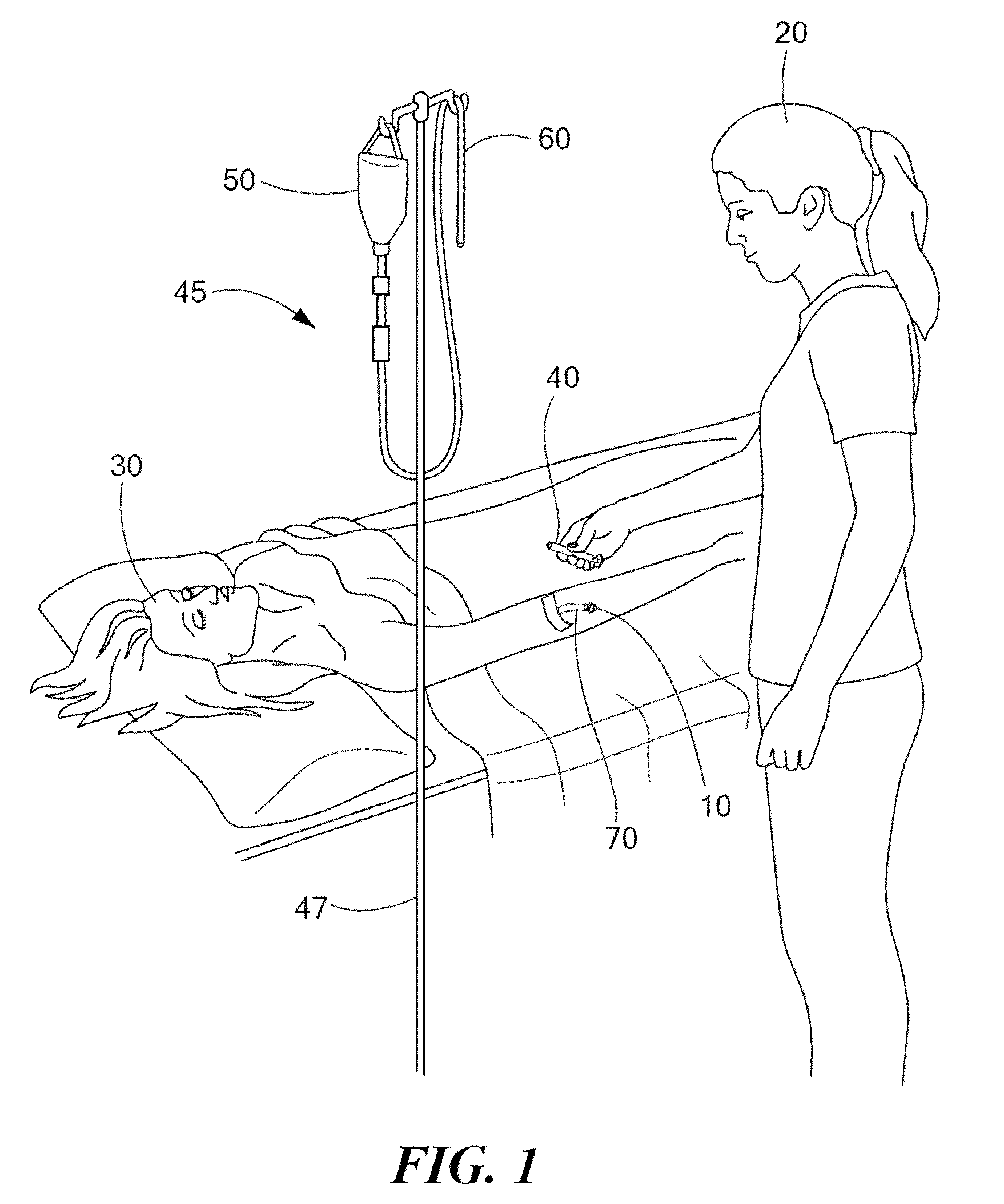
[0027]FIG. 1 schematically shows one illustrative use of a medical valve 10 configured in accordance with illustrative embodiments of the invention. In this example, a catheter 70 connects the valve 10 with a patient's vein (the patient is identified by reference number 30). Adhesive tape or similar material may be coupled with the catheter 70 and patient's arm to ensure that the valve 10 remains in place.

[0028]After the valve 10 is in place, a ...


PUM


Abstract

A medical valve has an open mode that permits fluid flow, and a closed mode that prevents fluid flow. To that end, the medical valve has a housing having an inlet and an outlet, and a resilient member within the housing. The resilient member has a body portion with a free state when undeformed by external mechanical forces and a deformed state when the valve is in the closed mode. The body portion is formed to return toward the free state as the valve transitions from the closed mode to the open mode and defining at least part of a fluid path through the valve.

Description

FIELD OF THE INVENTION[0001]The invention generally relates to medical valves and, more particularly, the invention relates to controlling fluid volumes within medical valves.BACKGROUND[0002]In general terms, medical valving devices often act as a sealed port that may be repeatedly accessed to non-invasively inject fluid into (or withdraw fluid from) a patient's vasculature. Consequently, a medical valve permits the patient's vasculature to be freely accessed without requiring such patient's skin be repeatedly pierced by a needle.[0003]Medical personnel insert a medical instrument into the medical valve to inject fluid into (or withdraw fluid from) a patient who has an appropriately secured medical valve. Once inserted, fluid may be freely injected into or withdrawn from the patient. Problems can arise, however, when the medical instrument is withdrawn from the valve. Specifically, suction produced by the withdrawing medical instrument can undesirably cause blood to be drawn proxima...

Claims


Application Information

Patent Timeline
Patent Type & Authority Patents(United States)
IPC IPC(8): A61M5/14A61M39/04A61M39/26
CPCA61M39/045A61M39/26A61M2039/262
Inventor ZEYTOONIAN, PAULKIMBALL, IAN
Owner NP MEDICAL
Learn More