Method for testing steel corrosion of reinforced concrete members

A technology for corrosion of reinforced concrete and steel bars, which is applied in the testing of basic structures, basic structure engineering, optical testing flaws/defects, etc. It can solve problems such as the inability to accurately judge the corrosion state of steel bars, the inability to establish corrosion of steel bars, and a single mathematical relationship. To achieve the effect of intuitive measurement, simple structure and easy judgment

Inactive Publication Date: 2007-08-01
NANJING UNIV OF AERONAUTICS & ASTRONAUTICS
View PDF0 Cites 40 Cited by
  • Summary
  • Abstract
  • Description
  • Claims
  • Application Information

AI Technical Summary

Problems solved by technology

The current optical fiber monitoring is mainly the monitoring of corrosion environmental parameters, and environmental monitoring is actually an indirect test method for judging the corrosion state of steel bars. Its defects are: 1) There are many environmental parameters that cause steel bar corrosion, such as the steel bar surface Humidity, O 2 , CO 2 , Cl - Concentration and pH value, etc. These factors influence each other, and a single mathematical relationship cannot be established with the corrosion of steel bars. It is necessary to comprehensively monitor the changes of these parameters and establish an expert system to reasonably judge the corrosion of steel bars. This method belongs to indirect monitoring of steel bar corrosion.
2) Optical fiber corrosion sensing technology for these parameters has slow signal response, narrow response range, and poor durability. There are still many practical problems in the application of concrete structures. Corrosion state

Method used


Image

  • Method for testing steel corrosion of reinforced concrete members

Examples


Embodiment Construction

[0027] The specific implementation manners of the present invention will be further described in detail below in conjunction with the accompanying drawings.

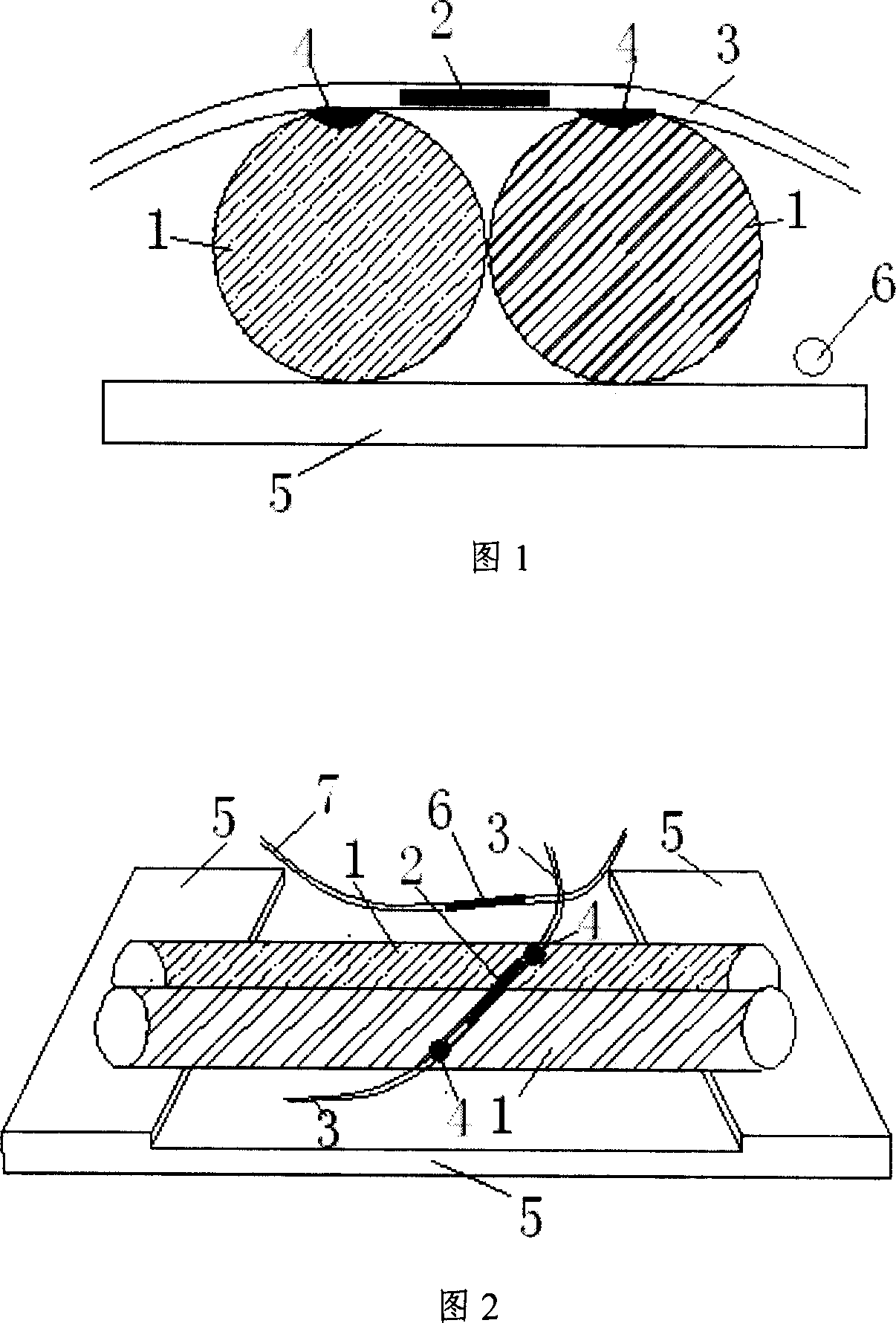
[0028] The sensor structure adopted by the present invention is shown in Fig. 1 and Fig. 2 .

[0029] Select two steel bars 1 of the same material as the steel bars used in the project, about 8cm in length, and slightly smooth the adjacent surface. At the same time, make a stainless steel base 5 with a slightly higher thickness at both ends of the base. Place the steel bars 1 as shown in the figure, and then fill them with permeability A good elastic filler is around the steel bar 1, but the top of the steel bar is reserved to fix the position of the steel bar, and then use epoxy resin 4 to paste the strained fiber grating 2 on the top of the two steel bars 1, and only paste two points, and use The strained optical fiber 3 is led out, the strained optical fiber 3 is covered with a heat-shrinkable tube, the strained optic...


PUM

PropertyMeasurementUnit
widthaaaaaaaaaa

Abstract

This invention relates to one steel concrete structure anti-erosion test method in structure engineer field, which comprises the following steps: a, sensor processing to parallel two steel bars in same materials for fixing and sticking the stress fiber grating to top end and putting one free temperature compensation fiber grating connected by the compensation fiber and sealing on shell; b, positioning the sensor and drilling it into concrete with stress fiber and temperature compensation connected to spectrum; c, monitoring by periods to test grating wave length volume and speed to infer anti-erosion degree and speed.

Description

technical field [0001] The invention relates to a method for detecting steel bar corrosion in reinforced concrete components, which can perform long-term detection of steel bar corrosion in reinforced concrete components in any environment without damaging the concrete surface, and is applied to the durability detection of reinforced concrete structures in the field of structural engineering and evaluation. Background technique [0002] Corrosion of steel bars in reinforced concrete is one of the main factors affecting the durability of structures. At present, the relatively mature non-destructive detection methods in its research methods mainly focus on the semi-potential method, concrete resistance method, etc., which determine the corrosion degree or speed of steel bars in concrete by measuring the electrochemical characteristics of the reinforced concrete corrosion system. Chemical detection methods, etc. The workload is heavy, and the test results are easily affected b...

Claims


Application Information

Patent Timeline
Patent Type & Authority Applications(China)
IPC IPC(8): G01N21/88E02D33/00
Inventor 吴瑾李俊高俊启
Owner NANJING UNIV OF AERONAUTICS & ASTRONAUTICS
Why Eureka
Try Eureka