Protective cover for a vehicle

a protective cover and vehicle technology, applied in the field of canopy type vehicle covers, can solve the problems of damage irreversible, device construction complicated, automobile surface finish degradation, etc., and achieve the effects of convenient use, low manufacturing cost, and simple construction

Inactive Publication Date: 2006-01-03
SHARAPOV SERGEY
View PDF26 Cites 41 Cited by
  • Summary
  • Abstract
  • Description
  • Claims
  • Application Information

AI Technical Summary

Benefits of technology

[0011]It is an object of the present invention to provide a canopy-type vehicle cover for protecting a vehicle from overheating, direct sun rays hail, etc., which is simple in construction, inexpensive to manufacture, convenient in use, occupies a small space in storage, and provides a ventilated space between the cover material and the upper surfaces of the vehicle body.
[0012]The protective cover of the invention is extremely simple in its structure and comprises a sheet or a web of a flexible material, which is subject to buckling when two opposite forces are applied to the opposite ends of the sheet. Preferably, the flexible material is stored in wound form, e.g., wound on a core and located in a cylindrical cassette with a slit for pulling out the flexible material. For retracting the material back into the cassette, the inner edge of the flexible sheet can be connected to a spiral spring. The flexible material itself should posses the property of buckling or curving up when it is pulled out and released from the cassette. This property can be imparted to the flexible material by pre-stressing the material or by providing it with longitudinally arranged resilient thin metal strips similar to the one used in a measure tape. The property of buckling up is enhanced by storing the flexible cover or the fabric with flexible metal strips, e.g., with springing properties, in a wound state.
[0015]In use, the cover of the invention forms a canopy-type protective shield above the vehicle with a space between the vehicle and the material of the cover sufficient for reliable ventilation of air. Such space is automatically formed and constantly maintained due to aforementioned pre-stressed condition of the flexible material of the cover. Storage of the sheet or web in a wound state enhances the aforementioned pre-stressed condition.

Problems solved by technology

Automobile surface finish degradation may be caused by sun rays, bird droppings, tree sap and pollens, snow and ice, frost, etc.
Unfortunately, there are many more cars than garages, so this solution leaves many cars outdoors.
This device has a complicated construction and can be blown out from the roof of the vehicle by gusts of winds.
If the metal spikes of the shield are bent, e.g., by the wind gusts, the damage becomes irreversible and the device has to be discarded.
While this design provided for motorized retraction of the cover, its storage box occupied a substantial amount of the trunk floor space, right in the center part of the trunk floor.
The '446 design is also necessarily complex because it uses an electric motor with an electrical wire running to the dash of the vehicle.
Furthermore, the cover of this type does not provide a space between the cover and the vehicle body so that the cover of this type does not protect the vehicle from heating.
A number of self-storing vehicle covers have been patented, but they all suffer from various problems.
While this design is provided for a storable cover, it is inconvenient and cumbersome to use, because after use, the cover has to be removed from the vehicle roof, manually rolled up, the bundle carried to the trunk of the vehicle, the trunk opened, the bundle placed inside, and the trunk closed.
One problem associated with this design is inconvenience: it takes time to fold and unfold, and store, the vehicle cover.
Since the entire body of the vehicle is covered from all sides, the spaces between the vehicle and the cover are not ventilated.
A disadvantage of this device is that for forming a ventilated space between the cover material and the surface of the vehicle body, the device requires the use of an additional structure in the form of foldable legs, which has to be permanently stored in the vehicle's trunk.

Method used


Image

  • Protective cover for a vehicle
  • Protective cover for a vehicle
  • Protective cover for a vehicle

Examples


Embodiment Construction

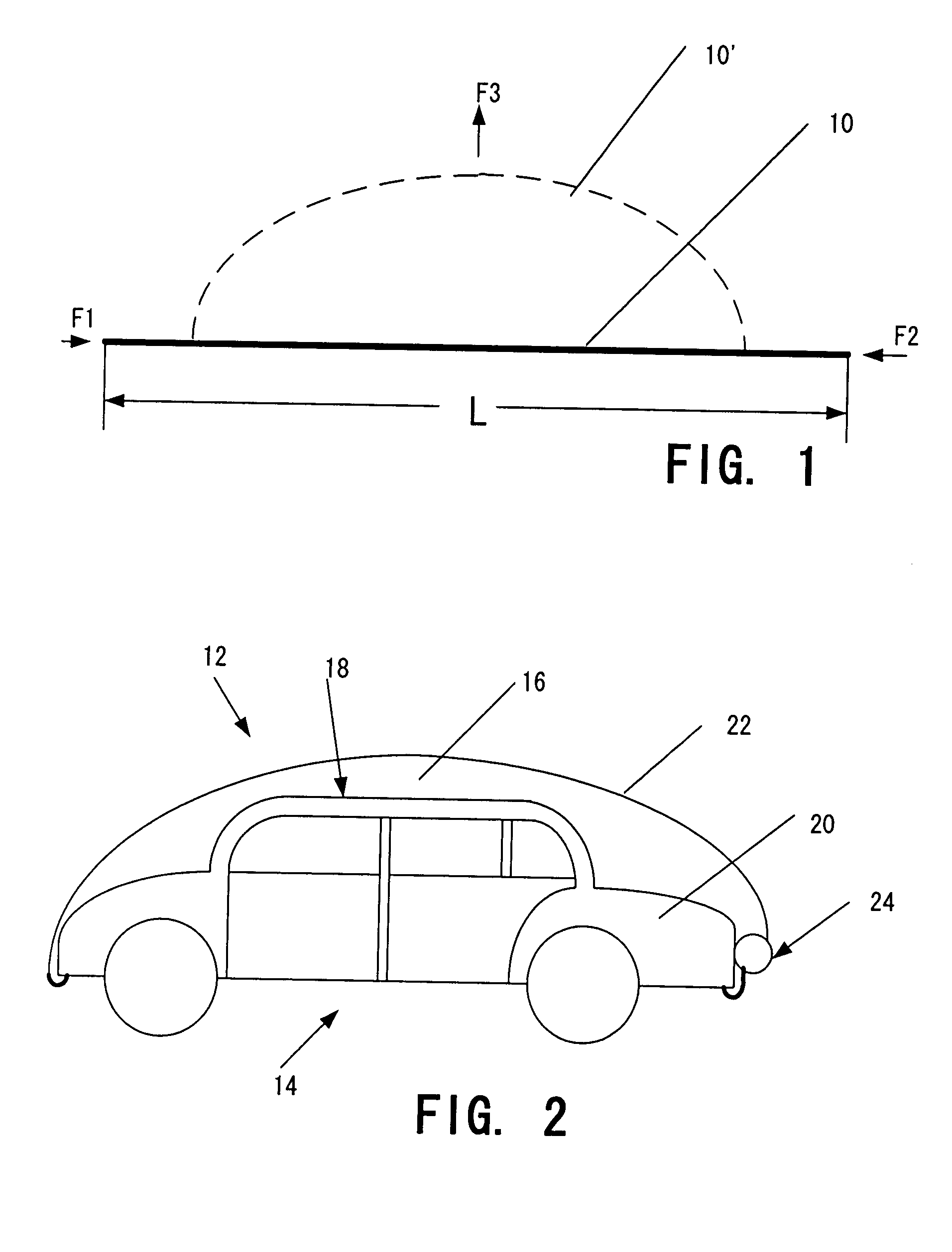
[0023]FIG. 1 is a schematic view illustrating the principle of the invention. In its simplest form, a device of the invention comprises a sheet 10 of a flexible material that possess some longitudinal rigidity, preferably to the extent sufficient for the sheet to resist sagging under the effect of gravity. The sheet 10 can be made, e.g., of a plastic, e.g., such as polypropylene, polyvinylchloride, etc., having a thickness, e.g., within the range of 0.1 mm to 10 mm. What is meant under the term “flexible material” is that when two opposite forces F1 and F2 sufficient to overcome longitudinal rigidity of the flexible sheet 10 are applied to the opposite edges of the sheet, the latter is buckled or curved upward and assumes the shape shown by a broken line 10′ in FIG. 1 under the effect of a resulting bending force F3 acting in the direction of arrow V shown in FIG. 1.

[0024]The sheet 10 can be prestressed so that in a free state it will automatically assume, under the effect of intern...


PUM


Abstract

A protective cover for a vehicle comprising a sheet or a web of a flexible material that possesses a property of buckling or curving in the upward direction from the vehicle with the formation of a canopy-type shield for protecting the vehicle from direct sun rays, birds' droppings, etc. The sheet has a length exceeding the length of the upper surface periphery of the vehicle so that the upwardly curved canopy is formed either by applying two oppositely directed forces to the opposite ends of the sheet or by prestressing the sheet. The sheet can be made from plastic or a fabric that incorporates springing metal strips that tend to curve upward when they are in a free state. The sheet can be conveniently stored in wound state in a cylindrical cassette. Storage of the flexible material in a wound state enhances the property of bucking or curving when the sheet is withdrawn from the cassette.

Description

FIELD OF THE INVENTION[0001]The present invention relates to vehicle covers, and in particular to canopy-type vehicle covers. The cover pertaining to the invention can be used for protection of a vehicle parked in open air from heat, sunrays, birds' droppings, and hail.BACKGROUND OF THE INVENTION[0002]In many countries, the automobile has become the most common method of transportation. Most automobiles are manufactured primarily of metal, and the metal is painted to protect it from oxidation and other influences detrimental to the finish. Automobile surface finish degradation may be caused by sun rays, bird droppings, tree sap and pollens, snow and ice, frost, etc.[0003]One way to prevent damage to the surface finish of an automobile is to store the car in a garage when it is not being used. Unfortunately, there are many more cars than garages, so this solution leaves many cars outdoors.[0004]U.S. Pat. No. 4,805,654 issued in 1989 to Kuo-Hsin-Wang provides an umbrella-type sun shie...

Claims


Application Information

Patent Timeline
Patent Type & Authority Patents(United States)
IPC IPC(8): B60J11/00
CPCB60J11/02
Inventor SHARAPOV, SERGEY
Owner SHARAPOV SERGEY
Why Eureka
Try Eureka