Pneumatic tire

a technology of pneumatic tires and lateral grooves, which is applied in the field of pneumatic tires, can solve the problems of increasing the amount of slippage on the road surface, the wear speed of the shoulder portion sh is relatively fast, and the lateral grooves to be arranged on the shoulder portion are worn out early, so as to reduce the amount of slippage, and increase the rigidity of the entire shoulder land portion and the corner portion

Active Publication Date: 2015-09-22
SUMITOMO RUBBER IND LTD
View PDF10 Cites 4 Cited by
  • Summary
  • Abstract
  • Description
  • Claims
  • Application Information

AI Technical Summary

Benefits of technology

[0007]Hence, an object of the present invention is to provide a pneumatic tire which can improve early wear performance of a shoulder portion and prevent early abrasion of lateral grooves, without deteriorating noise performance, basically by forming tread contour shape by a single arc, and regulating angle with respect to a tire circumferential direction, groove depth, and an inner end position of lateral grooves to be provided on the shoulder portion.
[0017]As described above, the present invention forms a contour line of a surface of a tread portion by an arc having a single radius of curvature. Therefore, a percentage of changes in a tire radius of the shoulder land portions can be kept low, and a difference in the amount of slippage of a tread surface and a road surface relative to a difference in positions in the tire axial di reaction can be made relatively small.
[0018]In addition, with the shoulder lateral grooves closer to the tire axial direction with its angle α with respect to the tire circumferential direction set to 80 to 90°, a corner portion sandwiched by the shoulder lateral groove and the shoulder circumferential main groove, for example, can be prevented from being shaped like a point of a knife and a starting point of wear. Furthermore, as the inner end of the shoulder lateral groove in the tire axial direction is spaced from the shoulder circumferential main groove, rigidity of the entire shoulder land portion as well as the corner portion can be increased. Thus, even if the groove depth of the deepest part of the shoulder lateral groove is set deeper than usual, such as 70 to 90% of the groove depth of the shoulder circumferential main groove, reduction in rigidity can be kept low. Coupled with the effect of reducing the amount of slippage by forming the tread contour shape with a single arc, the shoulder lateral grooves can be deepened while improving early wear performance. Thus, early abrasion of the shoulder lateral grooves can be controlled.

Problems solved by technology

However, in a tire with such a tread contour shape x1, a tire radius Tr on the side of a tread ground-contact edge Te significantly decreases, thus increasing amount of slippage with a road surface.
Hence, there is a problem that wear speed of the shoulder portion sh is relatively fast, and lateral grooves to be arranged on the shoulder portion are worn out early.
However, increased groove depth might not only degrade noise performance, but also increase an amount of deformation due to reduced block rigidity of the shoulder portion, thus further deteriorating wear resistance.

Method used


Image

  • Pneumatic tire
  • Pneumatic tire
  • Pneumatic tire

Examples


examples

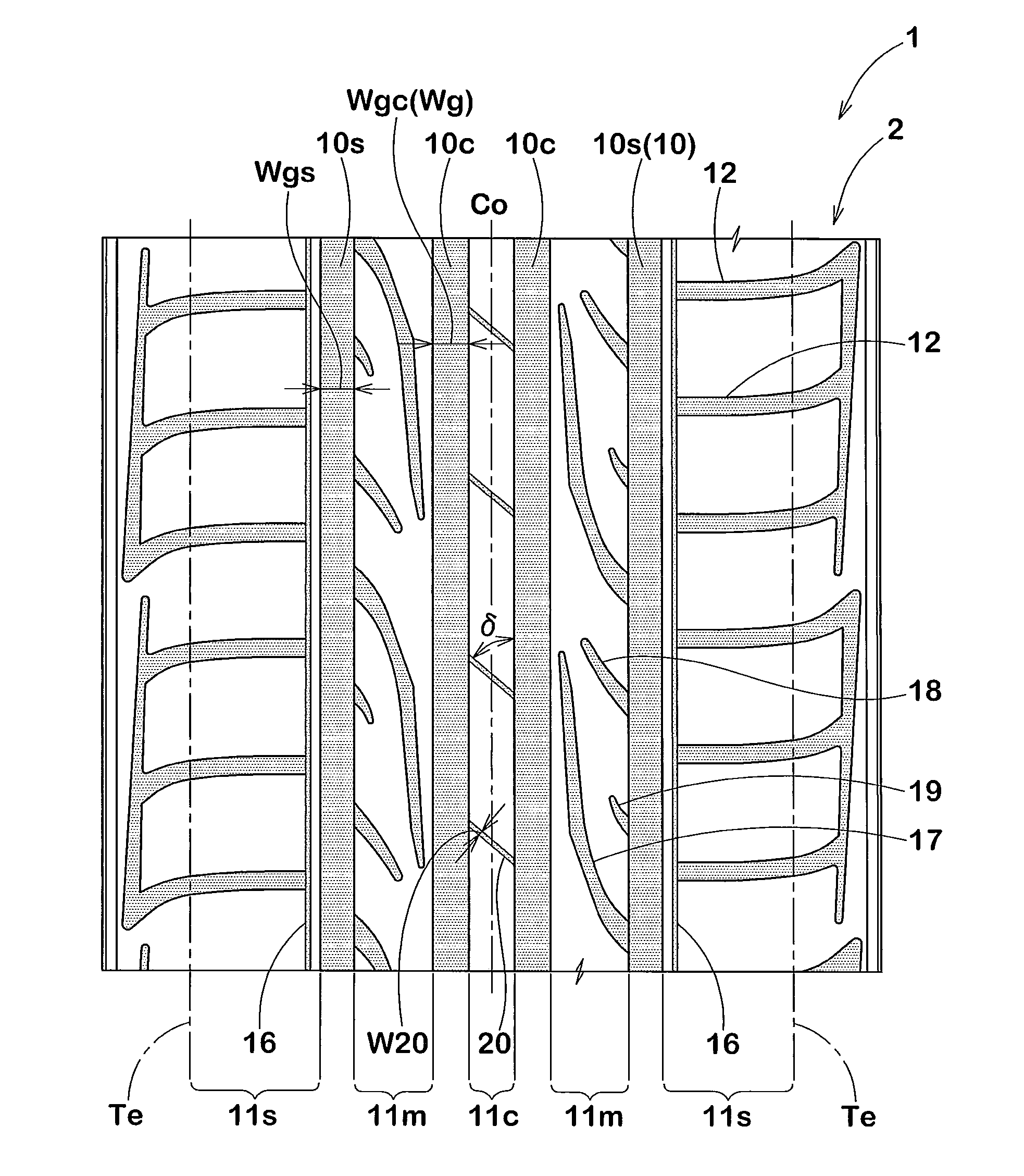
[0057]Radial tires of size 195 / 65R15 for passenger cars were prototyped with the tread pattern shown in FIG. 1 as a standard pattern based on the specifications in Table 1, and noise performance and early wear performance of respective sample tires were tested. Each tire has substantially same specifications, except for anything listed in Table 1. Shown below are common specifications.

[0058]Crown Circumferential Main Grooves

[0059]Groove width Wgc—10.5 mm

[0060]Groove depth Hgc—8.2 mm

[0061]Shoulder Circumferential Main Grooves

[0062]Groove width Wgs—8.2 mm

[0063]Groove depth Hgs—8.2 mm

[0064]Shoulder Lateral Grooves

[0065]Groove width W12—3.0 mm

[0066]Groove depth (maximum value)—Table 1

[0067]Middle Inclined Grooves

[0068]Groove width W17—4.5 mm

[0069]Groove depth (maximum value) H17—6.7 mm

[0070]Crown Lateral Grooves

[0071]Groove width W20—0.8 mm

[0072]Groove depth (maximum value) H20—4.0 mm

[0073]The sample tires were mounted on all wheels of the vehicle (displacement of 2000 cc) under the con...


PUM


Abstract

A tire contour shape is formed by a single arc in a condition in which tire flattening rate is more than 55% and less than 70% and internal pressure is 5%. Shoulder lateral grooves extend at an angle α of 80 to 90° from the axially outer side of the tread ground-contact edge to the axially inner side of the tire, and the tire axially inner ends terminate within the shoulder land portion. A tire axial distance Ds between the tire axially inner end and the shoulder circumferential main groove is in the range of 3.5 to 5.5 mm, the shoulder lateral groove has the deepest part where the groove depth is largest, and the groove depth of the deepest part is 70 to 90% of the groove depth of the shoulder circumferential main grooves.

Description

BACKGROUND OF THE INVENTION[0001]1. Field of the Invention[0002]The present invention relates to a pneumatic tire which has improved early wear performance in a shoulder portion, without deteriorating noise performance.[0003]2. Description of the Background Art[0004]In a pneumatic tire, in particular, a pneumatic tire for passenger cars, flattening of tire of 70% or less tends to proceed, for example, as vehicles have higher outputs and higher speeds in recent years. As shown in FIG. 8, conventionally, tread contour shape x1 of such a flattened tire, that is, the contour line x1 of an outer surface of a tread portion on a tire meridian cross section, is formed by connecting a plurality of arcs whose radii of curvature r differ such that the radius of curvature becomes smaller sequentially toward the axial outer side of the tire (See Japanese Patent Application Publication No. 10-181309, and Japanese Patent Application Publication No. 10-287106).[0005]However, in a tire with such a t...

Claims


Application Information

Patent Timeline
Patent Type & Authority Patents(United States)
IPC IPC(8): B60C11/04B60C11/00B60C11/03
CPCB60C11/0083B60C11/0306B60C11/042B60C2011/0365B60C2011/0369B60C2011/0372B60C2011/0374B60C2011/0381B60C3/04B60C9/08B60C11/04B60C11/13
Inventor TERASHIMA, MASAKI
Owner SUMITOMO RUBBER IND LTD
Why Eureka
Try Eureka