Multi-stage watertight chamber

a watertight chamber and multi-stage technology, applied in the direction of propulsive elements, vessel construction, marine propulsion, etc., can solve the problems of large space, difficult to prevent the high pressure liquid outside the waterproof structure, and damage to equipment or apparatus, so as to prevent damage to components and equipment

Inactive Publication Date: 2015-09-22
KANG CHIEN CHUNG
View PDF3 Cites 0 Cited by
  • Summary
  • Abstract
  • Description
  • Claims
  • Application Information

AI Technical Summary

Benefits of technology

[0008]An objective of the present invention is to provide a multi-stage watertight chamber 2, which comprises a first housing 20, an integrated shaft 22, a first rotary seal 202, a second housing 21, and a second rotary seal 212. The first housing 20 forms a first watertight chamber 201 to house components and equipment that needs to be isolated from fluid outside the housing. The second housing 21 forms a second watertight chamber 211 for storing water seepage from second rotary seal 212 and prevent damage to the components and equipment in the first watertight chamber 201.

Problems solved by technology

It is difficult to prevent the high pressure liquid outside the waterproof structure 1 from seeping in because the shaft 12 is usually rotating at high speed.
However, pressurized liquid in deep water could still leak into the housing 11 and cause damage to the equipment or apparatus installed in the housing 11 providing any flaw present with the rotary seal 14.
However, without a mean to visually verify the severity of the water ingress situation and a quick way to remove the accumulated liquid inside, it then requires relatively large space in the housing 11 to store water seepage until they can be removed.
In this case, a risk of damage to the equipment or apparatus in the housing 11 by liquid and its vapor can not be under estimated.

Method used


Image

  • Multi-stage watertight chamber
  • Multi-stage watertight chamber
  • Multi-stage watertight chamber

Examples


Embodiment Construction

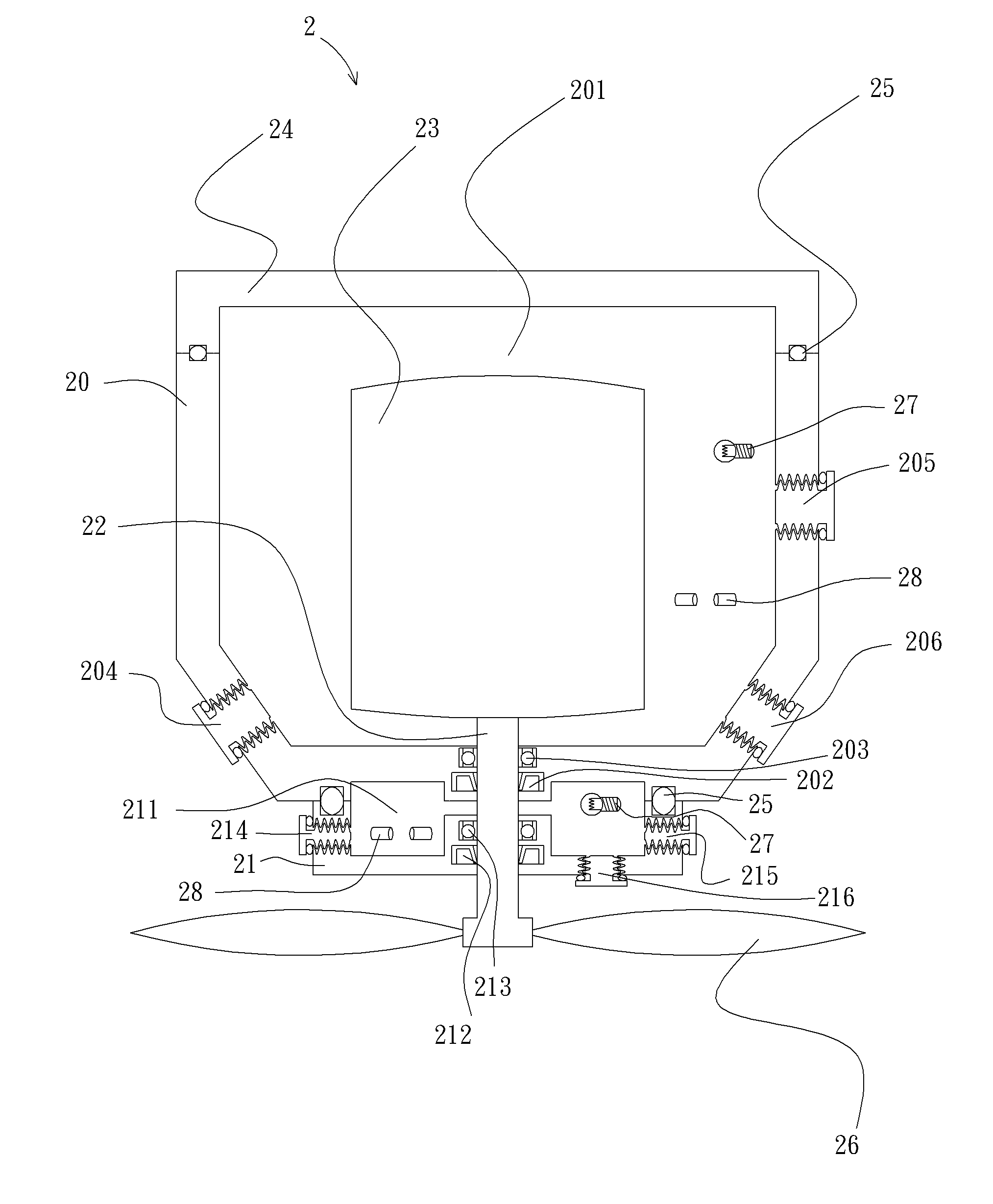
[0019]This invention, the multi-stage watertight chamber for an integrated shaft, provides a second watertight chamber formed adjacent to the first housings. The purpose of the second watertight chamber is to store water seepage preventing damage to devices installed in the first watertight chamber when rotary seals in either chamber starts to lose its ability to seal.

[0020]In the following description, this invention will be explained with reference to embodiments thereof. However, the description of these embodiments is only for purposes of illustration rather than limitation. It should be appreciated that in the following embodiments and attached drawings, elements unrelated to this invention are omitted from depictions; and dimensional relationships among individual elements in the attached drawings are illustrated only for ease of understanding, but not to limit the actual scale.

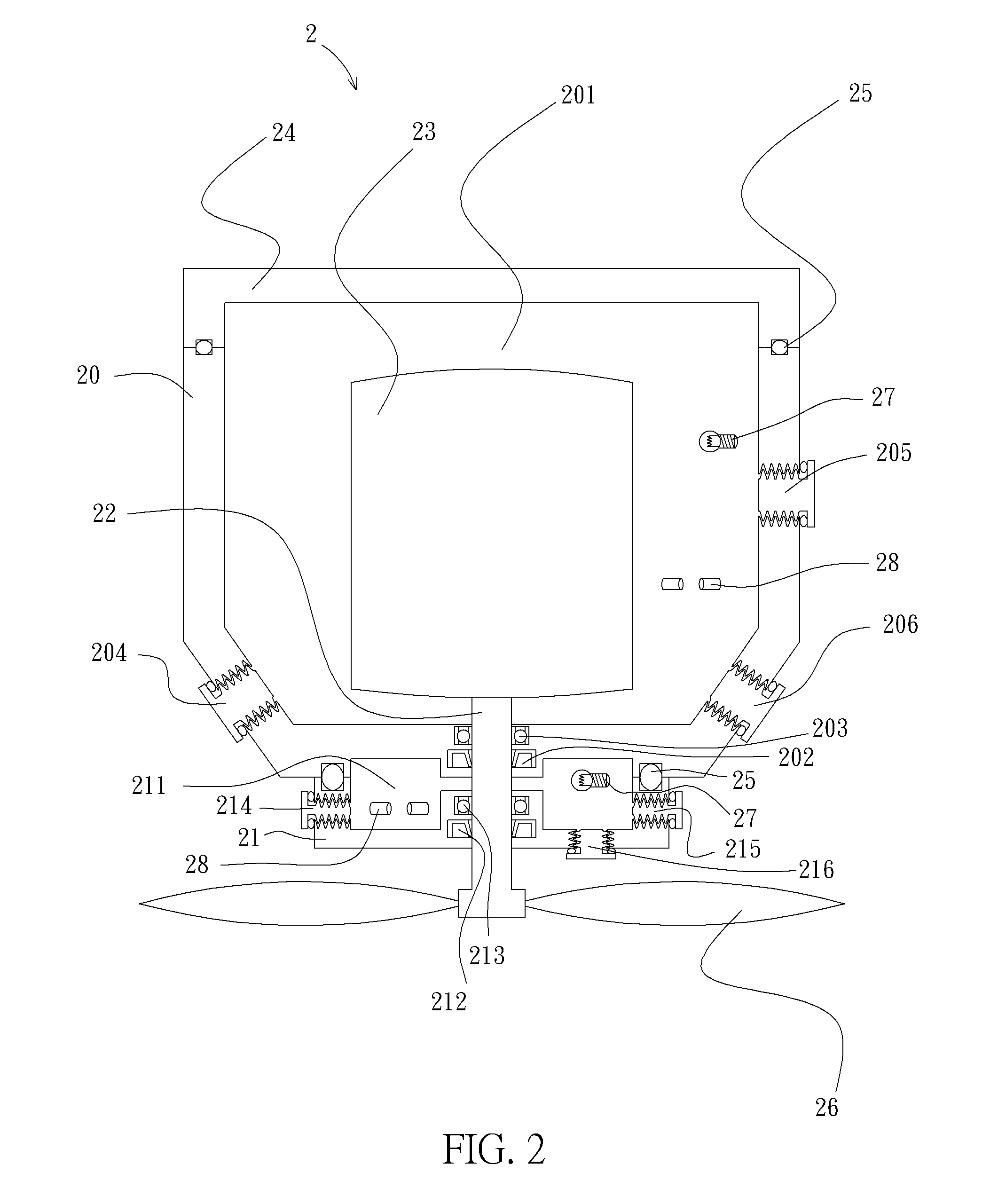
[0021]Referring to FIG. 2, a multi-stage watertight chamber 2 in the first embodiment includes a fir...


PUM


Abstract

A multi-stage watertight chamber is provided in this invention. The multi-stage watertight chamber comprises a first rotary seal, a second rotary seal, a first housing, a second housing, and an integrated shaft. The first and second rotary seals withstand external pressure to make sure watertight status is achieved when the integrated shaft rotates. The first housing forms a first watertight chamber. The integrated shaft protrudes through the first housing via the first rotary seal. The second housing is placed outside and adjacent to the first housing and forms a second watertight chamber. The first watertight chamber contains devices that must be isolated from liquid outside the first and second housings. The second watertight chamber is used to store water seeped through the second rotary seal and avoid causing damage directly to components and apparatus inside the first watertight chamber.

Description

[0001]This application claims the benefit of priority based on Taiwan Patent Application No 102213089, filed on Jul. 11, 2013, the contents of which are incorporated herein by reference in their entirety.CROSS-REFERENCES TO RELATED APPLICATIONS[0002]Not applicable.BACKGROUND OF THE INVENTION[0003]1. Field of the Invention[0004]The present invention relates to a multi-stage watertight chamber. More particularly, the present invention relates to a multi-stage watertight chamber that can store leaked-in water in one watertight chamber, and prevent damage to devices installed inside another watertight chamber.[0005]2. Descriptions of the Related Art[0006]FIG. 1 illustrates a waterproof structure 1 being applied to a shaft of motor equipment or apparatus in deep-water. The motor 10 must be protected inside the housing 11. A shaft 12 protrudes through the housing 11 to drive a load, such as a propeller 13. It is difficult to prevent the high pressure liquid outside the waterproof structur...

Claims


Application Information

Patent Timeline
Patent Type & Authority Patents(United States)
IPC IPC(8): B63H20/32B63H1/02B63H23/32B63H23/34B63H5/07
CPCB63H20/32B63H1/02B63H23/321B63B2750/00B63H5/07B63H23/34F16J15/16F16J15/18B63H2023/322B63H2023/327
Inventor KANG, CHIEN-CHUNG
Owner KANG CHIEN CHUNG
Why Eureka
Try Eureka