Unlock instant, AI-driven research and patent intelligence for your innovation.
Method for chemical vapor deposition control
Inactive Publication Date: 2015-09-22
TOKYO ELECTRON LTD
View PDF28 Cites 14 Cited by
Summary
Abstract
Description
Claims
Application Information
AI Technical Summary
This helps you quickly interpret patents by identifying the three key elements:
Problems solved by technology
Method used
Benefits of technology
Problems solved by technology
In addition, plasma excitation may activate film-forming chemical reactions that are not energetically or kinetically favored in thermal CVD.
Method used
Image
Click on the blue label to locate the original text in one second.
Reading with bidirectional positioning of images and text.
Examples
Embodiment Construction
[0032]In the following description, in order to facilitate a thorough understanding and for purposes of explanation and not limitation, specific details are set forth, such as a particular geometry of the processing system and descriptions of various components, as well as the methods and processes used therein.
[0033]However, one skilled in the relevant art will recognize that the various embodiments may be practiced without one or more of the specific details, or with other replacement and / or additional methods, materials, or components. In other instances, well-known structures, materials, or operations are not shown or described in detail to avoid obscuring aspects of various embodiments of the invention. Similarly, for purposes of explanation, specific numbers, materials, and configurations are set forth in order to provide a thorough understanding of the invention. Nevertheless, the invention may be practiced without specific details. Furthermore, it is understood that the vari...
PUM
Property
Measurement
Unit
pressure
aaaaa
aaaaa
width
aaaaa
aaaaa
width
aaaaa
aaaaa
Abstract
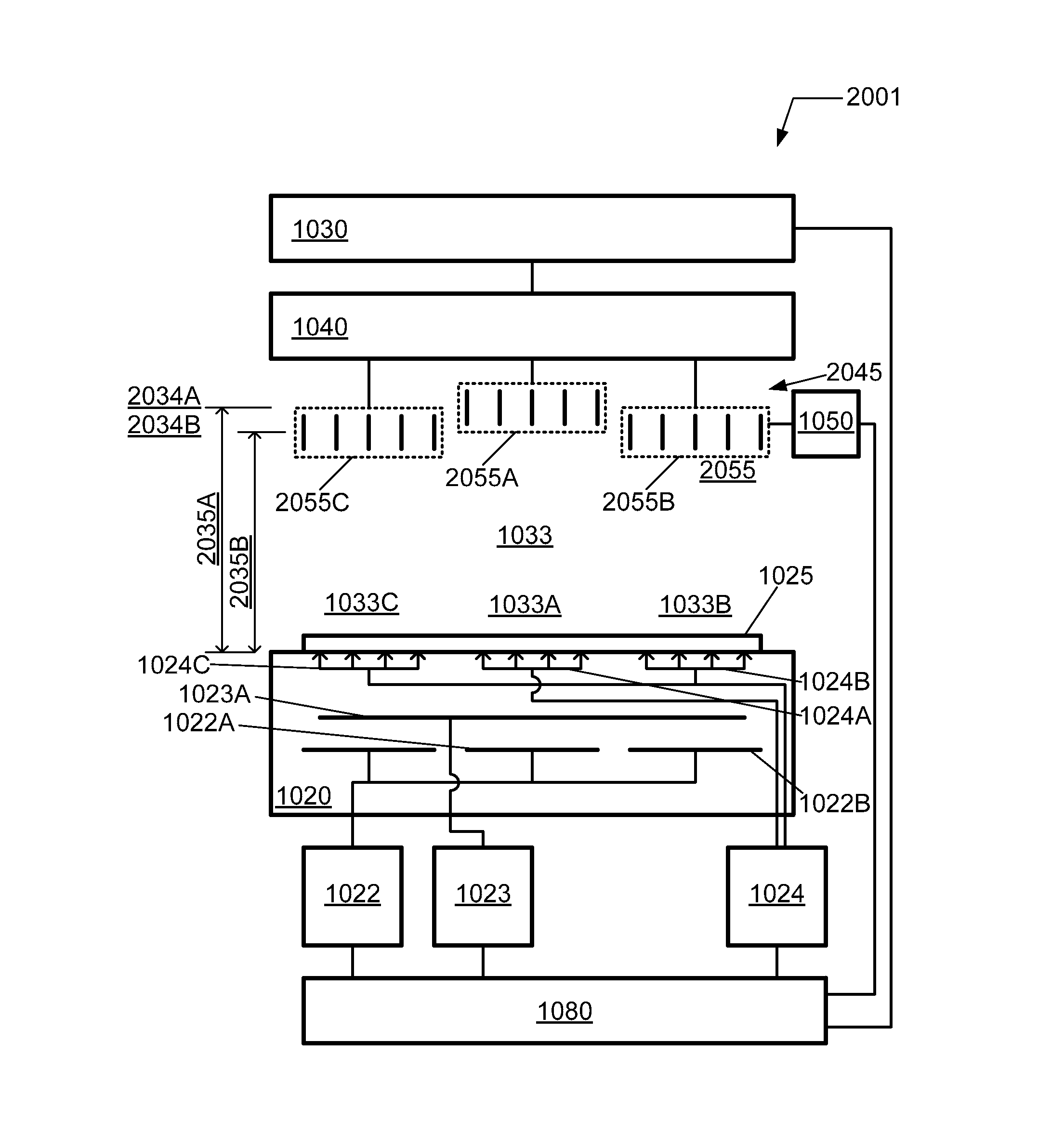
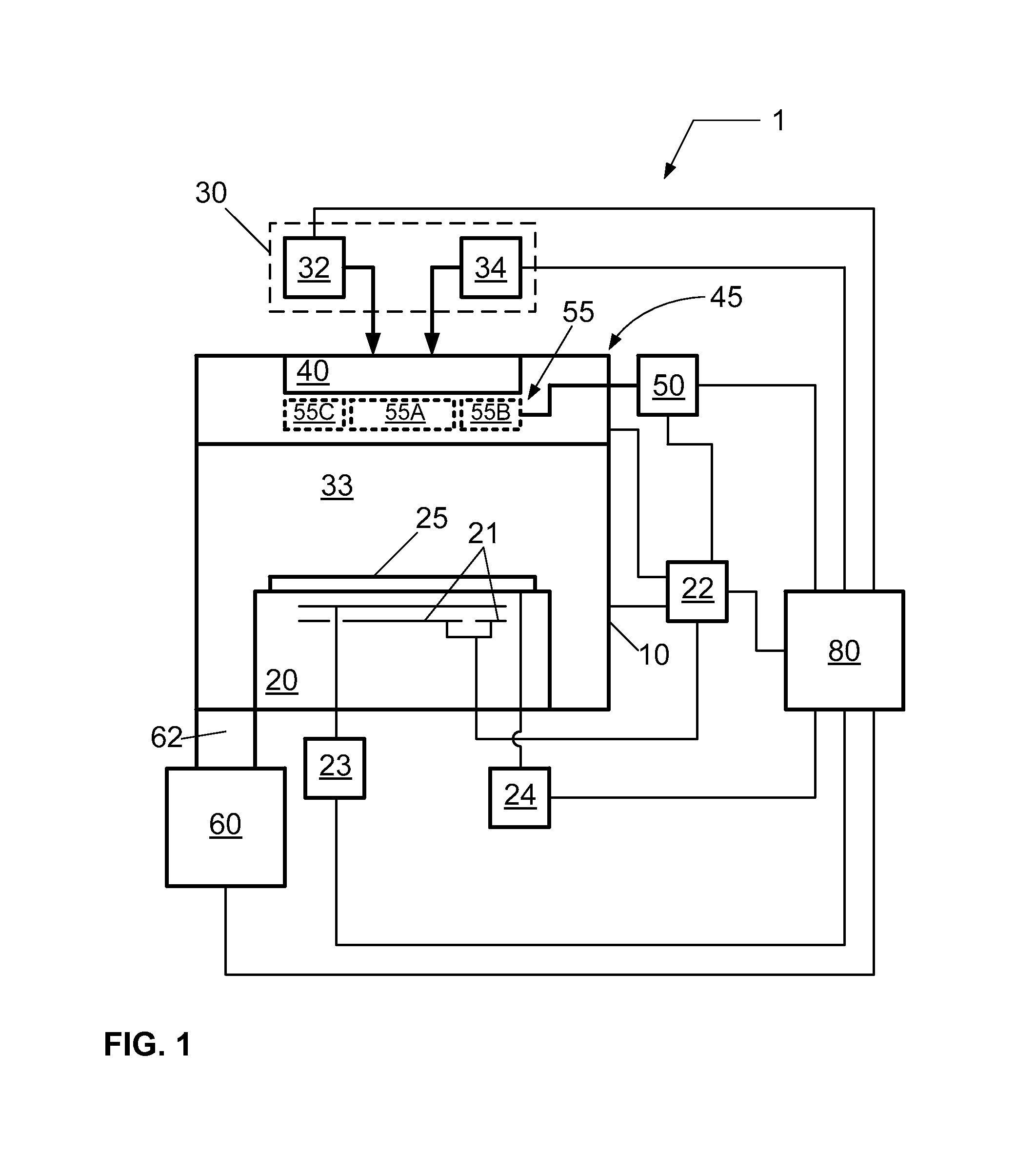
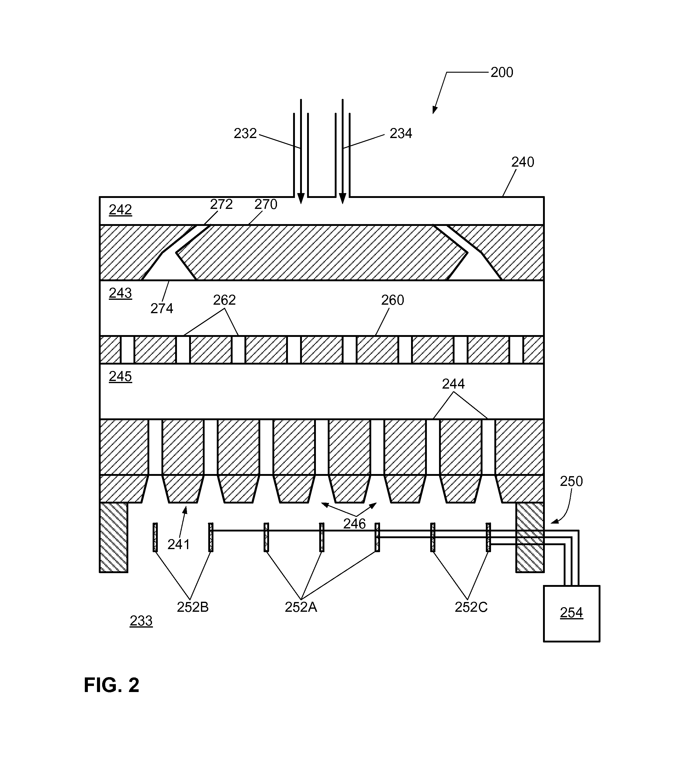
A method of depositing a thin film on a substrate in a deposition system is described. The method includes disposing a gas heating device comprising a plurality of heating element zones in a deposition system, and independently controlling a temperature of each of the plurality of heating element zones, wherein each of the plurality of heating element zones having one or more resistive heating elements. Additionally, the method includes providing a substrate on a substrate holder in the deposition system, wherein the substrate holder has one or more temperature control zones. The method further includes providing a film forming composition to the gas heating device coupled to the deposition system, pyrolyzing one or more constituents of the film forming composition using the gas heating device, and introducing the film forming composition to the substrate in the deposition system to deposit a thin film on the substrate.
Description
CROSS-REFERENCE TO RELATED APPLICATIONS[0001]This application is related to U.S. patent application Ser. No. 12 / 814,278, entitled “APPARATUS FOR CHEMICAL VAPOR DEPOSITION CONTROL”, filed on Jun. 11, 2010, now U.S. Pat. No. 8,852,347 issued on Oct. 7, 2014; U.S. patent application Ser. No. 11 / 693,067, entitled “VAPOR DEPOSITION SYSTEM AND METHOD OF OPERATING”, filed on Mar. 29, 2007 and now abandoned; U.S. patent application Ser. No. 12 / 044,574, entitled “GAS HEATING DEVICE FOR A VAPOR DEPOSITION SYSTEM AND METHOD OF OPERATING”, filed on Mar. 7, 2008, now U.S. Pat. No. 8,291,856 issued on Oct. 23, 2012; and U.S. patent application Ser. No. 12 / 559,398, entitled “HIGH TEMPERATURE GAS HEATING DEVICE FOR A VAPOR DEPOSITION SYSTEM”, filed on Sep. 14, 2009, now U.S. Pat. No. 8,272,347 issued Sep. 25, 2012. The entire content of these applications are herein incorporated by reference in their entirety.BACKGROUND OF THE INVENTION[0002]1. Field of Invention[0003]The invention relates to a pro...
Claims
Application Information
Patent Timeline
Application Date:The date an application was filed.
Publication Date:The date a patent or application was officially published.
First Publication Date:The earliest publication date of a patent with the same application number.
Issue Date:Publication date of the patent grant document.
PCT Entry Date:The Entry date of PCT National Phase.
Estimated Expiry Date:The statutory expiry date of a patent right according to the Patent Law, and it is the longest term of protection that the patent right can achieve without the termination of the patent right due to other reasons(Term extension factor has been taken into account ).
Invalid Date:Actual expiry date is based on effective date or publication date of legal transaction data of invalid patent.
