Building construction system

a construction system and building technology, applied in the direction of girders, walls, joists, etc., can solve the problems of uneven slab edge formation, and uneven slab edge formation

Inactive Publication Date: 2015-09-22
BRADY TODD A
View PDF17 Cites 9 Cited by
  • Summary
  • Abstract
  • Description
  • Claims
  • Application Information

AI Technical Summary

Benefits of technology

[0008]The present invention is directed to a building construction system that allows for adjustably connecting building components. The present invention is directed toward forming an even surface along an uneven slab edge, and for securely attaching this structure to a slab edge without causing any breakage or spalling.
[0010]It is another purpose of the present invention to have elements of the building construction system provide means to secure the system to the slab edge without breaking the slab edge by attaching the system to foam inserts embedded within the concrete slab instead of attaching the system directly to the slab. By having the building construction system attached to foam inserts, and not concrete, the occurrence of breakage, chipping, and spalling on the slab is is reduced when the straight track is placed over the uneven slab edge.
[0014]The stud attachment plate of the elongated track extends perpendicularly from the web, and is capable securing studs along the elongated track by attachment members such as screws, nails, pins, bolts, or the like. Since the web of the elongated track has an even surface (as opposed to an uneven slab edge surface) the use of the stud attachment plate on the even surfaced track allows the installer to place studs evenly along an uneven slab edge, since the slab edge is overlaid by the even surfaced elongated track. The elongated track can be placed and secured at various distances from the slab edge to accommodate the uneven front edge of the slab, leading to the formation of adjustment gap spaces between the elongated track and the slab edge.

Problems solved by technology

One situation that occurs when creating a concrete slab is that the edge of the slab may be formed unevenly.
This often occurs because a margin of error from ¼ inch to 2 inches is considered acceptable when the framing for the slab is constructed before the concrete is poured.
This imprecision results in an uneven slab edge.
Even when done carefully, the edges of the slab usually do not line up perfectly due to the imprecision of the multiple slabs placed adjacent to each other.
If studs and walls are installed on an uneven slab edge, then the result is a crooked wall.
Although secondary structures can be used to cover an uneven slab edge to create an even surface, often these secondary attachment structures may cause the slab edge to break or cause spalling.

Method used


Image

  • Building construction system
  • Building construction system
  • Building construction system

Examples


Embodiment Construction

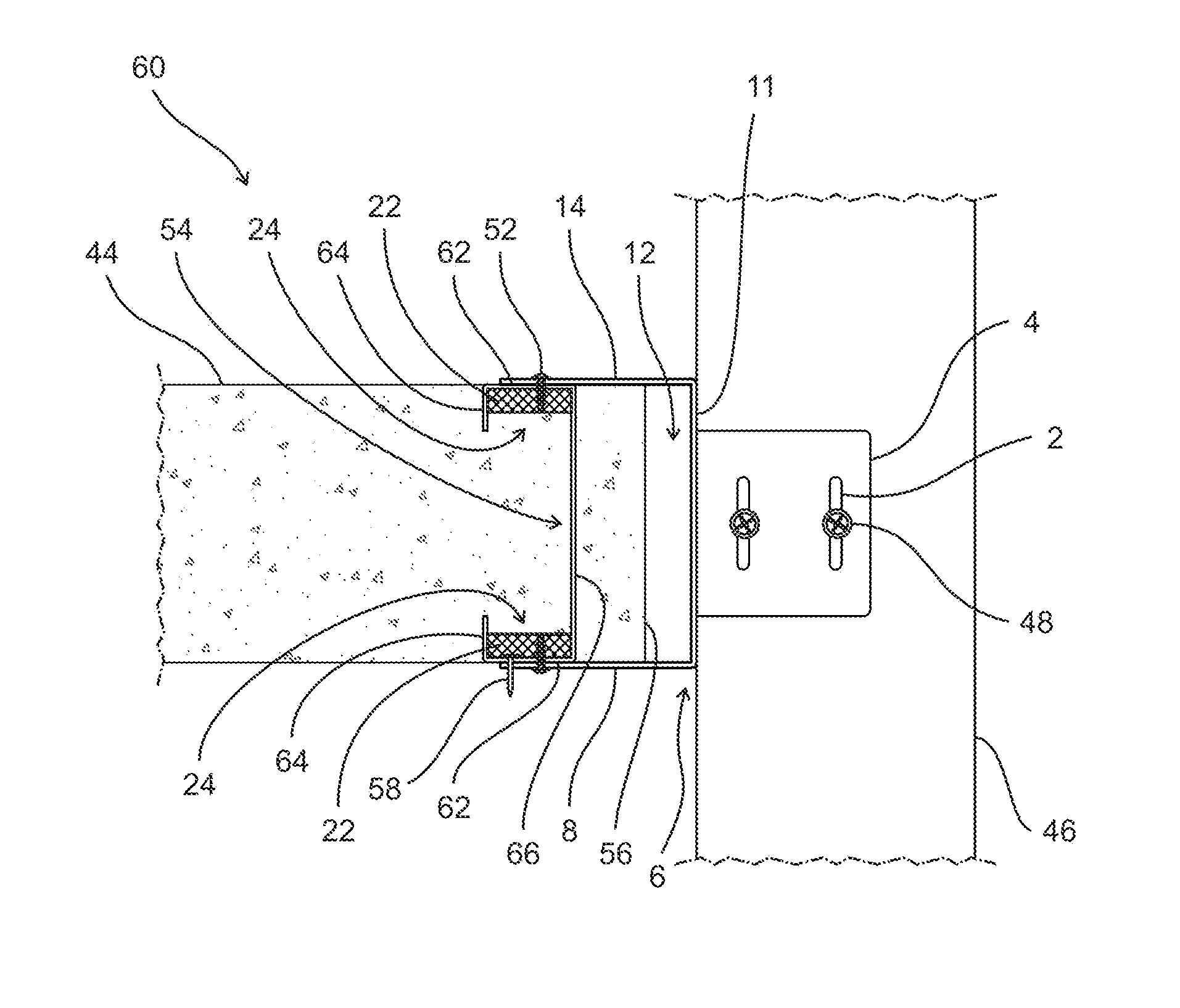
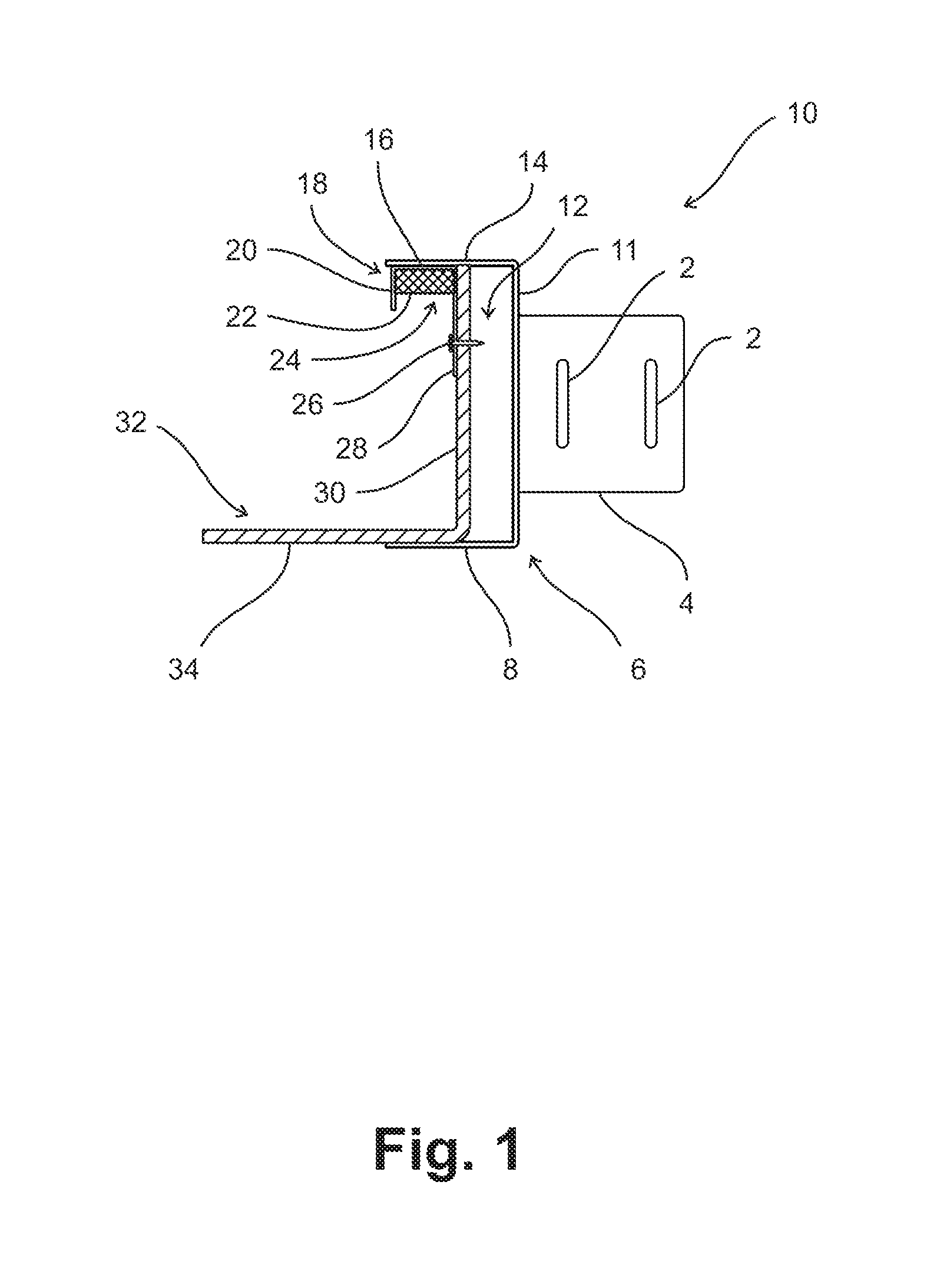
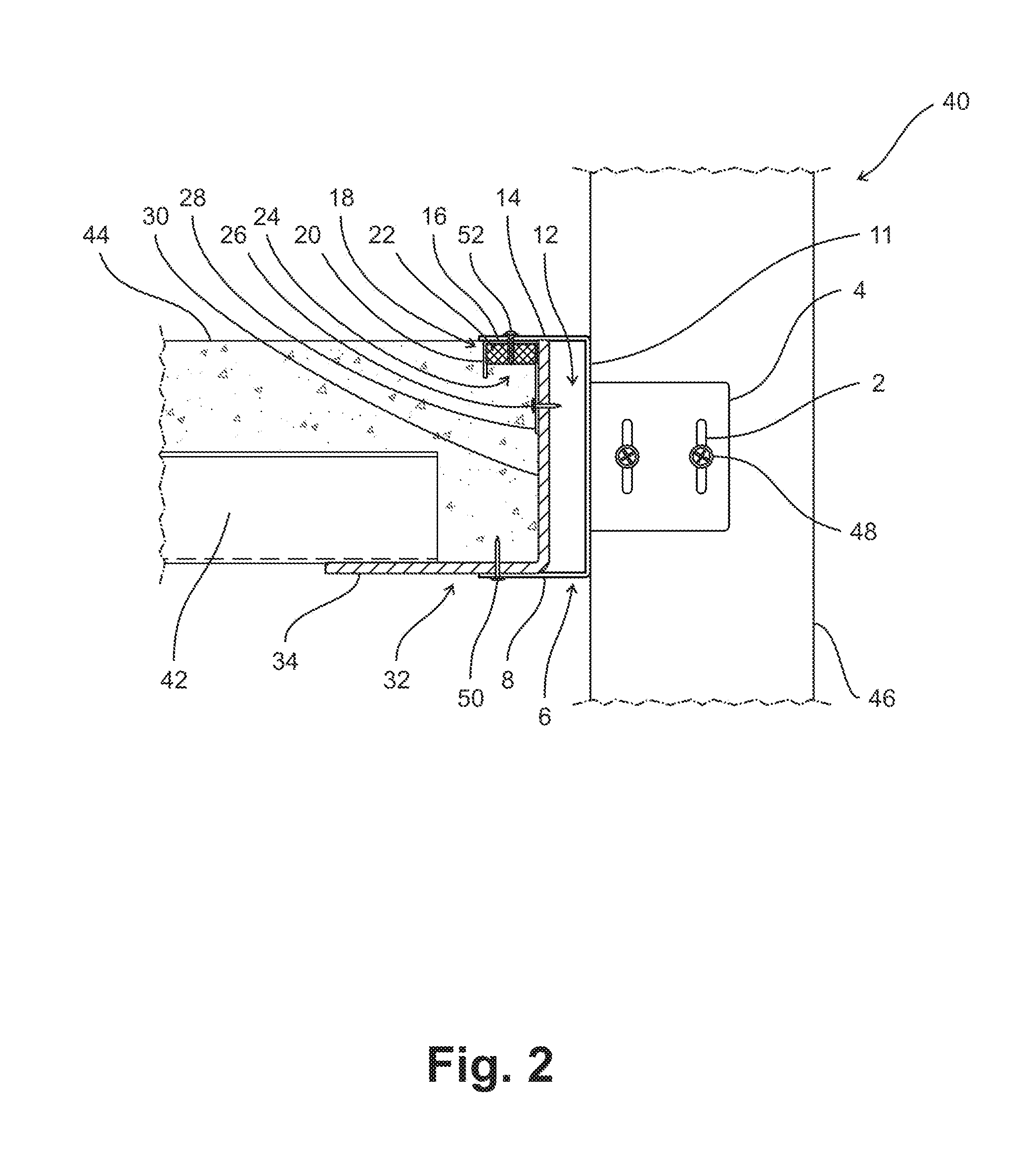
[0032]The invention now will be described more fully hereinafter with reference to the accompanying drawings, in which embodiments of the invention are shown. This invention may, however, be embodied in many different forms and should not be construed as limited to the embodiments set forth herein. Rather, these embodiments are provided so that this disclosure will be thorough and complete, and will fully convey the scope of the invention to those skilled in the art.

[0033]It will be understood that when an element is referred to as being “on” another element, it can be directly on the other element or intervening elements may be present therebetween. As used herein, the term “and / or” includes any and all combinations of one or more of the associated listed items.

[0034]It will be understood that, although the terms first, second, third etc. may be used herein to describe various elements, components, regions, layers and / or sections, these elements, components, regions, layers and / or ...


PUM


Abstract

A building construction system is provided having an elongated track (bypass clip track) that overlays a front edge of a concrete slab. The elongated track provides an even flat surface along an uneven concrete slab because the elongated track can be placed at adjustable distances from slab edges that may be uneven. The track is secured to a bracketing structure that has foam inserts that become embedded within the top and / or bottom surface of the concrete slab after the concrete hardens. By attaching the track to these foam inserts instead of the concrete directly, breakage or spalling of the slab edge is reduced. Studs are then attached to a stud attachment plate extending from the track, such that thereafter, a wall or façade may be attached to the track that overlays the uneven slab edge.

Description

CROSS-REFERENCE TO RELATED APPLICATIONS[0001]This application is a divisional of U.S. patent application Ser. No. 14 / 263,833, filed Apr. 28, 2014, the contents of which are incorporated herein in its entirety.BACKGROUND OF THE INVENTION[0002]1. Field of the Invention[0003]This invention relates to a building construction, and more particularly, to a bracketing system for creating an even secondary edge along an uneven slab edge for attaching studs.[0004]2. Background Information[0005]Concrete slabs form a part of the load bearing structure of buildings and are used to support non-load bearing walls. In designing the edge of the slab, there are two typical approaches: the slab cantilevers over the spandrel beam and loads are applied to the overhang, or loads are carried by a structural steel plate or assembly attached to a spandrel beam. Furthermore, a slab must also have sufficient strength to carry a load without increasing the thickness of the floor slab system. If the slab does n...

Claims


Application Information

Patent Timeline
Patent Type & Authority Patents(United States)
IPC IPC(8): E04B1/18E04B1/41E04B1/24E04B1/38
CPCE04B1/40E04B1/24E04B2001/405E04B2001/2415E04B2/88E04C3/07E04C2003/0473E04F13/0808E04B1/41E04B1/388E04B2001/389
Inventor BRADY, TODD A.
Owner BRADY TODD A
Why Eureka
Try Eureka