
Piston pump with cam actuated valves

a technology of cam-actuated valves and piston pumps, which is applied in the direction of piston pumps, positive displacement liquid engines, machines/engines, etc., can solve the problems of increased noise, increased noise, and significant noise generation of piston pumps during conventional modes of operation

Inactive Publication Date: 2015-09-22
CATERPILLAR INC
View PDF11 Cites 1 Cited by
  • Summary
  • Abstract
  • Description
  • Claims
  • Application Information

AI Technical Summary

Benefits of technology

The present disclosure is about a piston pump and a method of controlling it. The pump includes a housing, cylinder barrel, pistons, intake cam ring, exhaust cam ring, intake valves, exhaust valves, intake ports, out ports, intake valves, and exhaust valves. The intake valves open and close to regulate fluid supplied to the pistons, and the exhaust valves do the same with fluid discharged by the pistons. The method involves actuating the pistons to cause them to engage in reciprocating motion, and regulating the fluid supplied and discharged by changing the position of the intake and exhaust cam rings. The technical effects are improved regulation of fluid supply and discharge for better performance of the piston pump.

Problems solved by technology

Piston pumps can generate a significant amount of noise during conventional modes of operation.
Overpressurization or underpressurization of the piston chamber relative to the hydraulic system has been identified as a source of noise in piston pumps.
An overpressurized piston chamber produces a pressure “overshoot” upon opening to the outlet, producing an audible noise.
Such noise can increase as the pressure difference between the piston chamber and the outlet increases.
Piston chamber underpressurization may produce noise because the rate of pressure change within the piston chamber is abrupt, and the higher system pressure impacts into the piston chamber.
Conventional methods to reduce piston pump noise have been somewhat ineffectual.
However, such proposals are not feasible in that loads placed on port plates during operation are usually extremely high.
Such high loads make it nearly impossible to move or adjust the port plates during operation.
However, none of these approaches have resulted in effectively eliminating noise arising from such piston pumps.

Method used


Image

  • Piston pump with cam actuated valves
  • Piston pump with cam actuated valves
  • Piston pump with cam actuated valves

Examples


Embodiment Construction

[0014]Reference will now be made in detail to exemplary embodiments, which are illustrated in the accompanying drawings. Wherever possible, the same reference numbers will be used throughout the drawings to refer to the same or like parts.

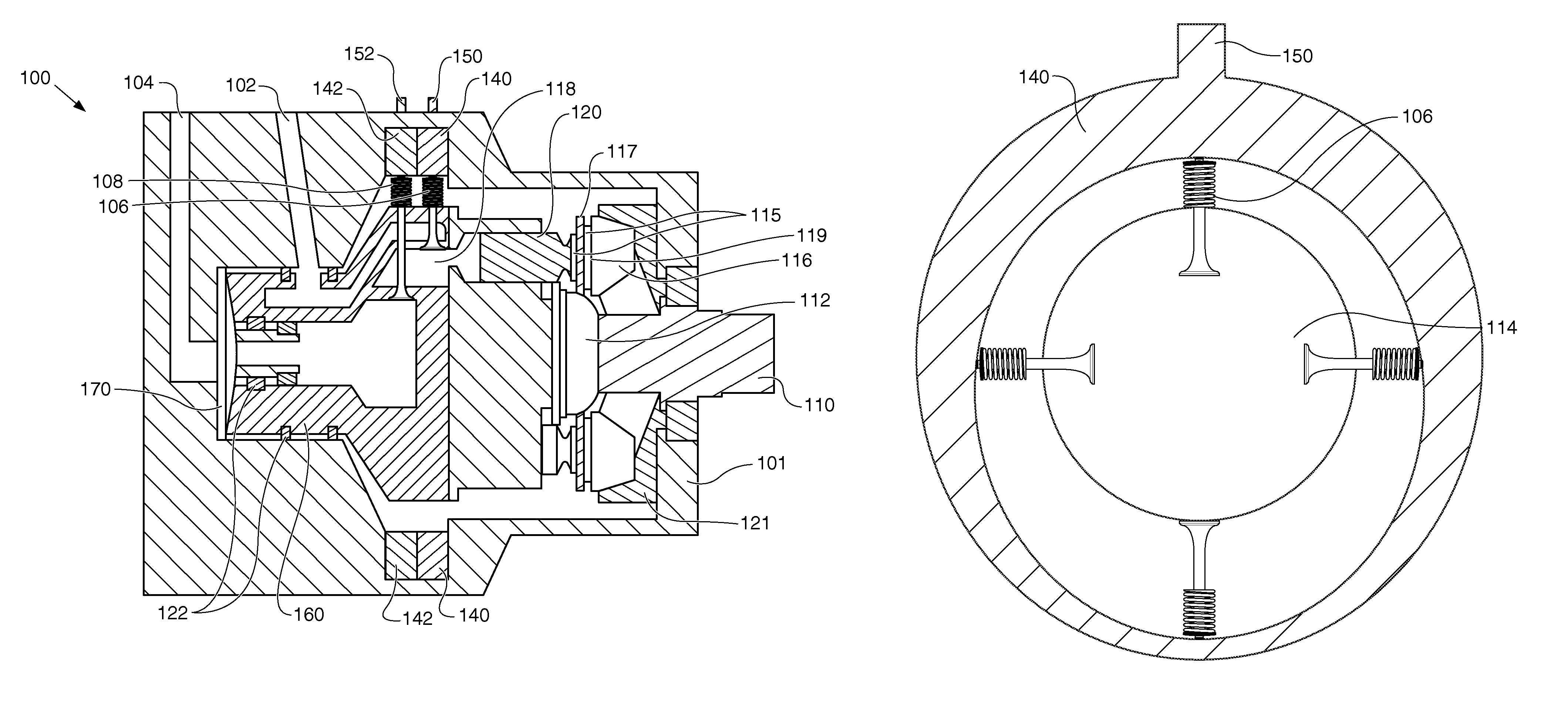
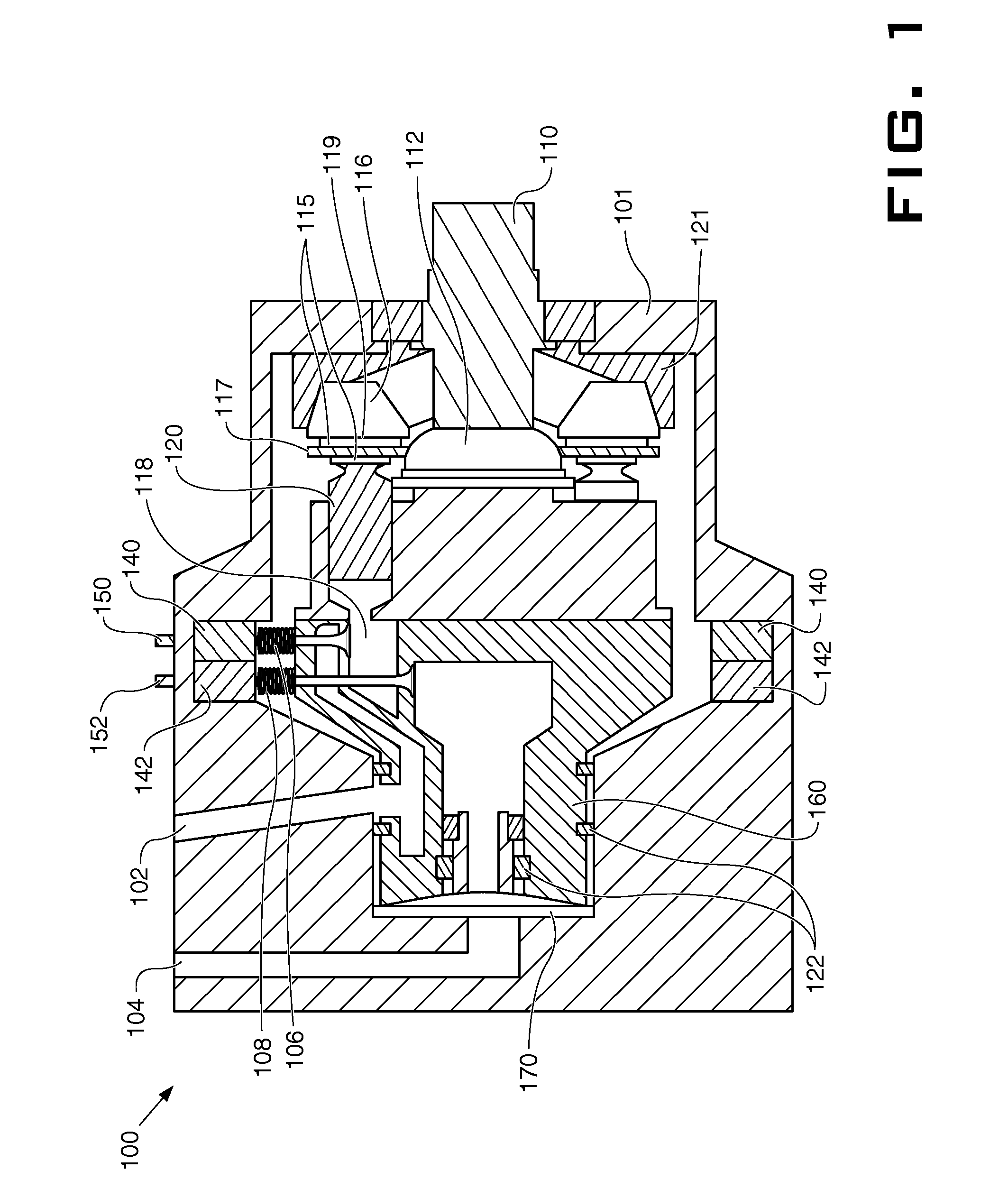
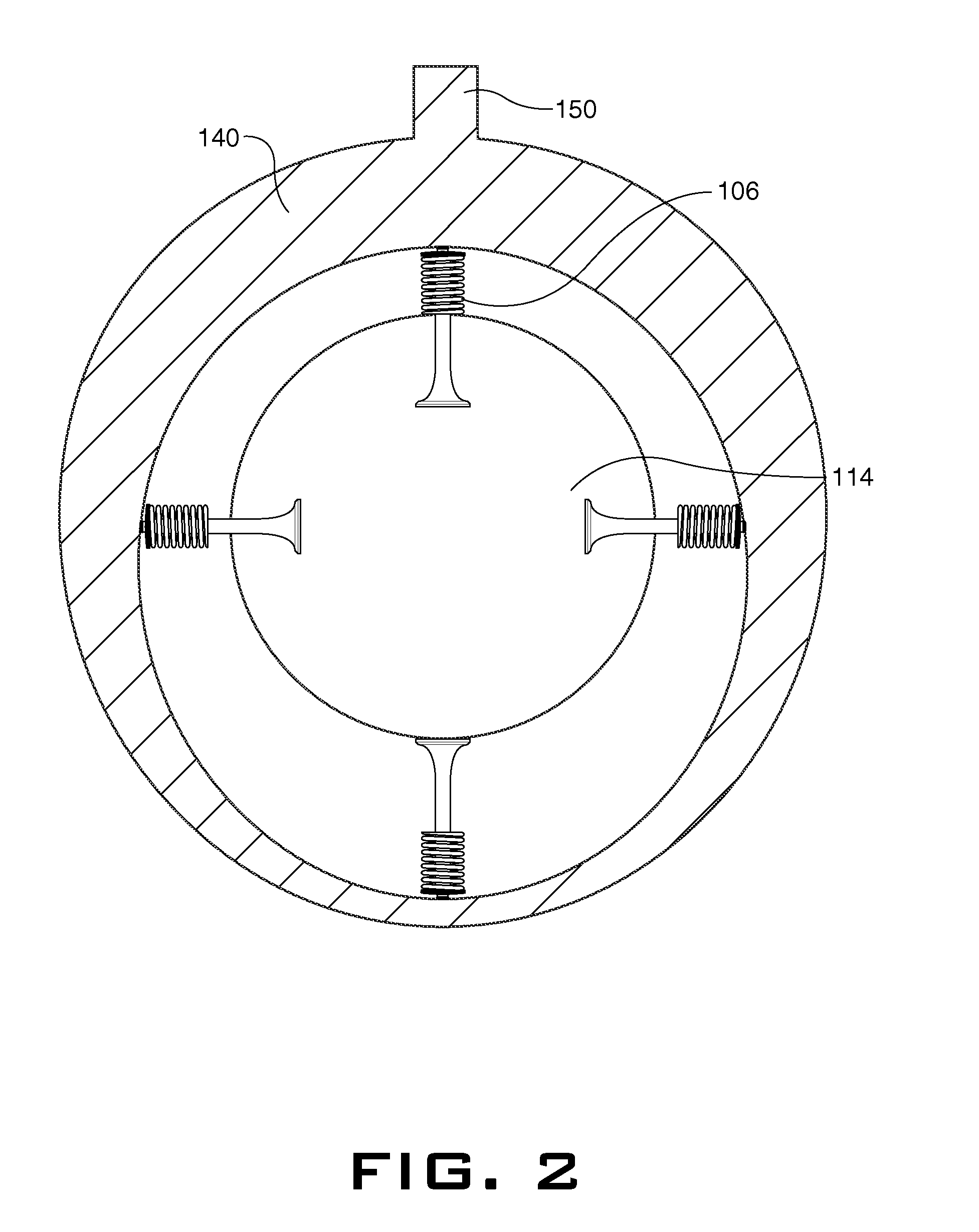
[0015]FIG. 1 illustrates a cross-sectional view of a piston pump according to one embodiment. The piston pump 100 may include a housing 101, drive shaft 110, cylinder barrel 114, and a plurality of pistons 120. The cylinder barrel 114 is positioned within the housing 101 and adapted to rotate about an axis of rotation by a drive shaft 110. The drive shaft 110 can be rotatably supported in the housing 101, and extends from and is integral with the cylinder barrel 114. The plurality of pistons 120 may be arranged in the cylinder barrel 114. In an embodiment, there may be a number of pistons such as 5, 7, 9 etc. Each piston 120 can be configured to reciprocate within the cylinder barrel 114 in a direction parallel to the axis of rotation of the cylind...


PUM


Abstract

A method of controlling a piston pump is disclosed. The method includes actuating a plurality of pistons housed within a cylinder barrel to cause each of the plurality of pistons to engage in reciprocating motion. Fluid supplied to each of the pistons may be regulated by changing a clock position of an intake cam ring to cause a plurality of intake valves to open and close relative to the clock position of the intake cam ring. Fluid discharged by each of the pistons may be regulated by changing a clock position of an exhaust cam ring to cause a plurality of exhaust valves to open and close relative the clock position of the exhaust cam ring.

Description

TECHNICAL FIELD[0001]The present disclosure relates generally to a piston pump, and more particularly, to a piston pump for use in a hydraulic system.BACKGROUND[0002]Piston pumps can generate a significant amount of noise during conventional modes of operation. Increasingly stringent regulations that are designed to limit overall noise in the workplace have created a demand for piston pumps that operate at lower sound levels.[0003]There are a number of ways by which piston pumps generate noise. For example, when piston pumps operate, rotating pistons draw in hydraulic fluid through an inlet slot, typically at atmospheric pressure. After the pumping chamber is closed to the inlet, the piston passes bottom dead center (BDC). As the piston moves back to top dead center, it pressurizes and discharges the fluid into the outlet. As the fluid in the pumping chamber is pressurized during the transition just after BDC, the hydraulic fluid reaches a particular chamber pressure, after which it...

Claims


Application Information

Patent Timeline
Patent Type & Authority Patents(United States)
IPC IPC(8): F04B1/30F04B1/20F04B7/00F04B1/32
CPCF04B1/2042F04B1/2035F04B1/32F04B7/008F04B7/0057
Inventor HENDERSON
Owner CATERPILLAR INC
Learn More