
Shadow detection method and device

a detection method and shadow technology, applied in image enhancement, image analysis, instruments, etc., can solve the problems of segmentation error, affecting the accuracy of object detection, and bringing a lot of difficulties and restrictions to computer-based image processing, so as to achieve fast speed of related calculation and low cost of related calculation. , the effect of robust illumination

Inactive Publication Date: 2015-09-22
RICOH KK
View PDF7 Cites 2 Cited by
  • Summary
  • Abstract
  • Description
  • Claims
  • Application Information

AI Technical Summary

Benefits of technology

This method enables accurate and efficient shadow detection and removal in 3D space, improving object detection and tracking accuracy, and is robust to illumination variations and depth map quality, with reduced computational cost and complexity.

Problems solved by technology

The existence of shadow brings a lot of difficulties and restrictions to computer-based image processing.
In particular, in object detection performed on an image, the existence of shadow may negatively influence the accuracy of the object detection.
For example, a segmentation method is easily influenced by shadow, thereby generating a segmentation error.
In addition, an object detection algorithm or object tracking algorithm is also easily influenced by shadow, thereby generating an incorrect detection result or incorrect tracking result.
However, these kinds of methods may be dramatically influenced by environmental background complexity, and may be easily influenced by lighting conditions.
However, in this method, it is necessary to obtain the corresponding illumination-invariant image, and the removal of shadow is restricted by the obtention of the corresponding illumination-invariant image and the quality of the corresponding illumination-invariant image.
Furthermore, the application of this method is very limited; for example, this method is only suitable to be used in shadow detection of a projection exhibition system.
However, this method relies on the quality of the two background models too much, and it is difficult to acquire a dense depth background model by utilizing a well-used two-lens camera.
As a result, this method is not valid in some cases.

Method used


Image

  • Shadow detection method and device
  • Shadow detection method and device
  • Shadow detection method and device

Examples


Embodiment Construction

[0028]In order to let those people skilled in the art better understand the present invention, hereinafter the present invention will be concretely described on the basis of the drawings and various embodiments.

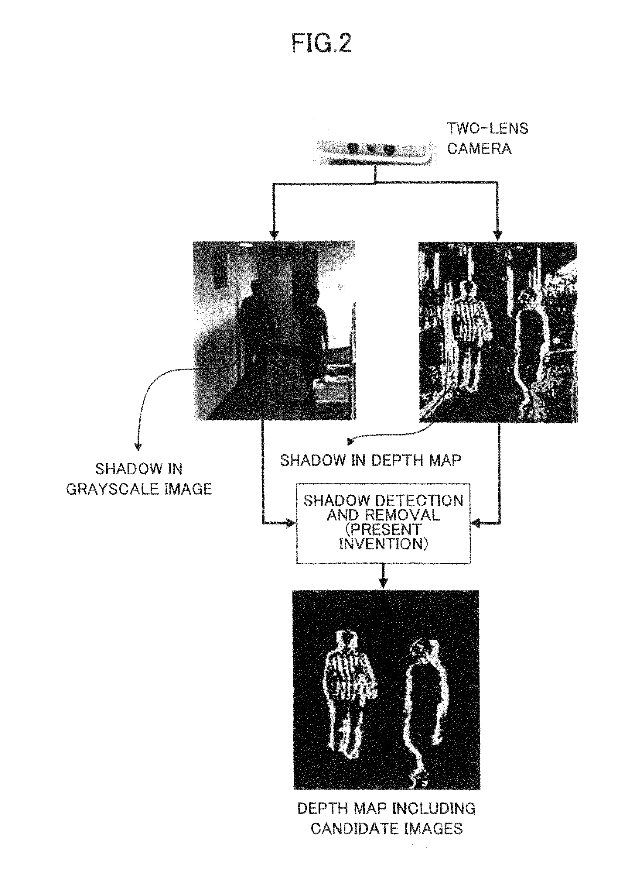
[0029]FIG. 2 illustrates a process of shadow detection and removal according to an embodiment of the present invention.

[0030]As shown in FIG. 2, first, a color image, a grayscale image, or a depth map of a scene, captured by a two-lens camera is obtained, and second, the obtained one is input to a shadow detection and removal system according to an embodiment of the present invention. After that, in this shadow detection and removal system, a shadow detection and removal method according to an embodiment of the present invention is carried out with respect to the input color image, grayscale image, or depth map so as to obtain an image including only one or more candidate objects. Here it should be noted that in the present invention, what is proposed is a shadow detection an...


PUM


Abstract

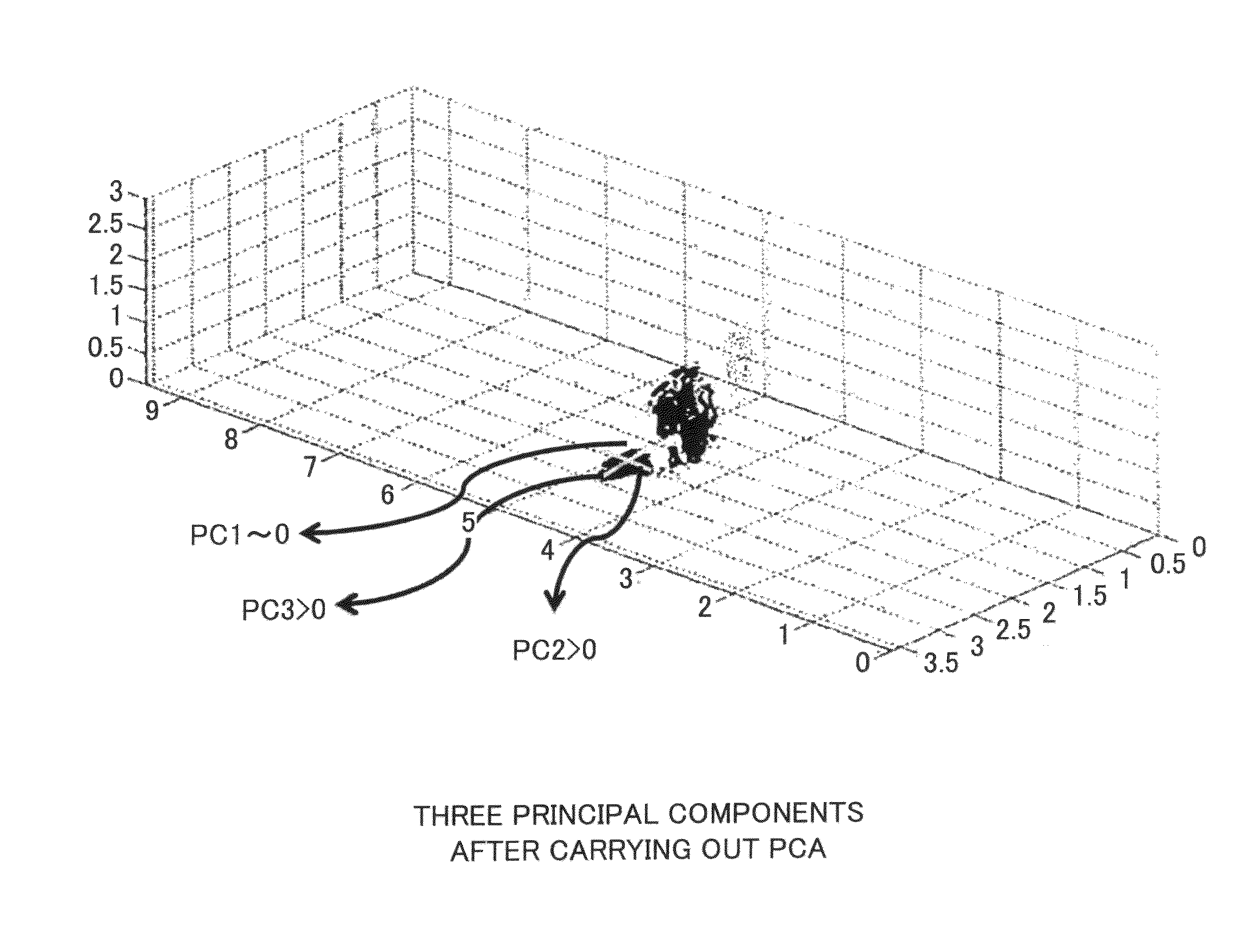
Disclosed are a shadow detection method and device. The method includes a step of obtaining a depth / disparity map and color / grayscale image from a two-lens camera or stereo camera; a step of detecting and acquiring plural foreground points; a step of projecting the acquired plural foreground points into a 3-dimensional coordinate system; a step of carrying out, in the 3-dimensional coordinate system, a clustering process with respect to the projected plural foreground points so as to divide the projected plural foreground points into one or more point clouds; a step of calculating density distribution of each of the one or more point clouds by adopting a principal component analysis algorithm so as to obtain one or more principal component values of the corresponding point cloud; and a step of determining, based on the one or more principal component values, whether the corresponding point cloud is a shadow.

Description

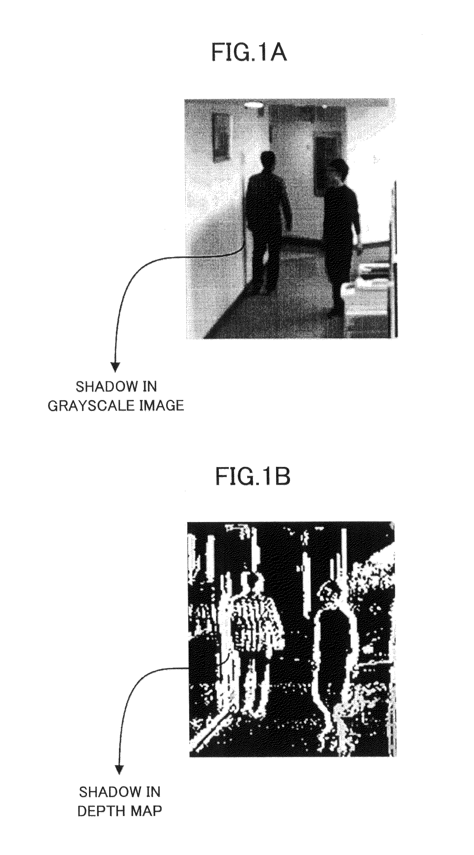
BACKGROUND OF THE INVENTION[0001]1. Field of the Invention[0002]The present invention generally relates to a shadow detection method and device, and more particularly relates to a method and device for detecting and removing shadow by utilizing a color image / grayscale image and depth map / disparity map captured by a two-lens camera or stereo camera.[0003]2. Description of the Related Art[0004]Shadow is a kind of familiar natural phenomenon, and often exists in a color image or grayscale image captured by a well-used camera. FIGS. 1A and 1B illustrate that shadow exists in a grayscale image and depth image captured by a two-lens camera, respectively. The existence of shadow brings a lot of difficulties and restrictions to computer-based image processing. In particular, in object detection performed on an image, the existence of shadow may negatively influence the accuracy of the object detection. For example, a segmentation method is easily influenced by shadow, thereby generating a s...

Claims


Application Information

Patent Timeline
Patent Type & Authority Patents(United States)
IPC IPC(8): G06T5/00G06T7/00
CPCG06T5/008G06T7/0081G06T2200/04G06T2207/10012G06T2207/10024G06T2207/20144G06T2207/30196G06T2207/30232G06T7/11G06T7/194G06T5/94
Inventor FAN, SHENGYINWANG, XINWANG, QIANQIAO, GANG
Owner RICOH KK
Learn More