Control synchronization for high-latency teleoperation

a high-latency, control-synchronized technology, applied in the field of teleoperation systems, can solve the problems of mismatch between user intent and resulting robot motion, not always realizing the ideal scenario, and no longer accurately representing the current pose or state of the robotic system

Active Publication Date: 2015-09-29
HARRIS CORP
View PDF9 Cites 42 Cited by
  • Summary
  • Abstract
  • Description
  • Claims
  • Application Information

AI Technical Summary

Problems solved by technology

However, due to data link latency and low bit rates this ideal scenario is not always realized.
When data link latency is substantial it can lead to a mismatch as between user intent and resulting robot motion.
The latency of this feedback data means that it may no longer accurately represent a current pose or state of the robotic system.
Such latent imagery can therefore cause a user to misunderstand the control inputs that are required to achieve a desired end.
Ultimately, latent feedback data as described herein will negatively impact teleoperation, potentially causing damage to the robotic system and / or objects in the robot environment.

Method used


Image

  • Control synchronization for high-latency teleoperation
  • Control synchronization for high-latency teleoperation
  • Control synchronization for high-latency teleoperation

Examples


Embodiment Construction

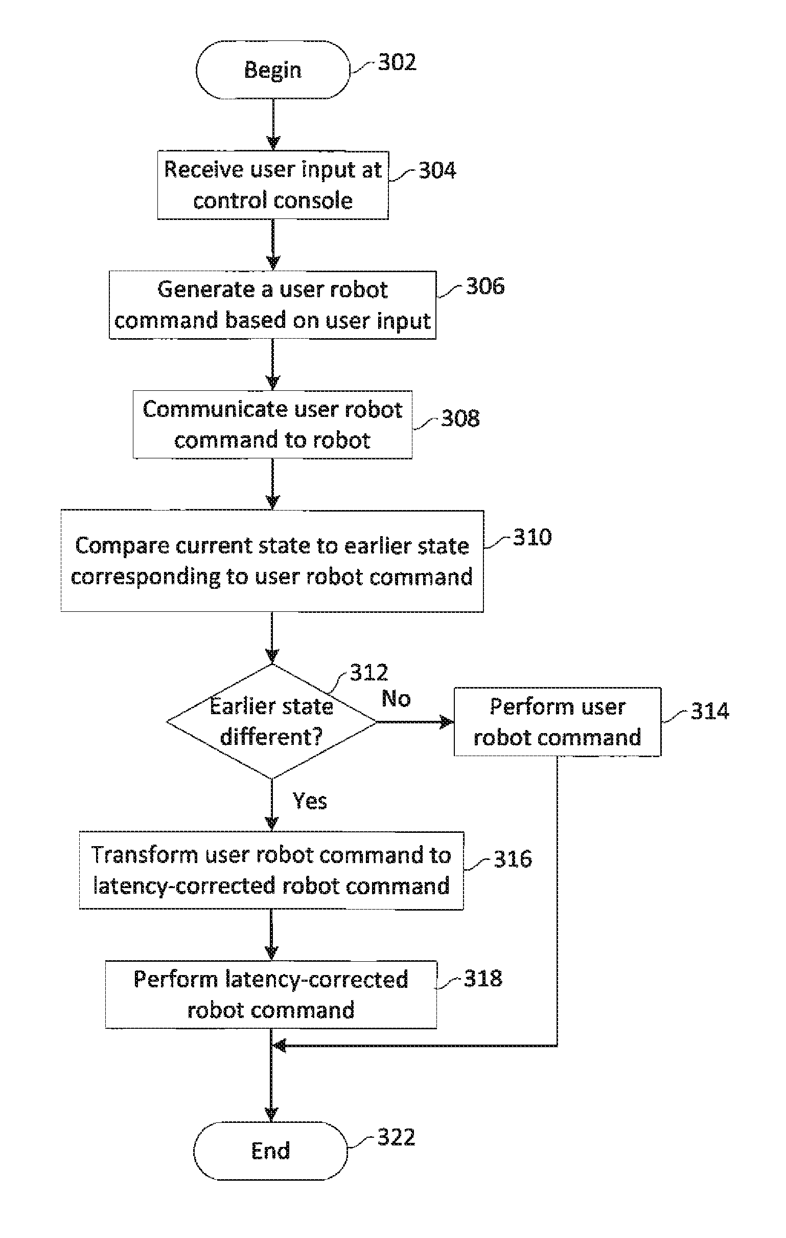
[0020]The invention is described with reference to the attached figures. The figures are not drawn to scale and they are provided merely to illustrate the instant invention. It should be understood that numerous specific details, relationships, and methods are set forth to provide a full understanding of the invention. One having ordinary skill in the relevant art, however, will recognize that the invention can be practiced without one or more of the specific details or with other methods. In other instances, well-known structures or operations are not shown in detail to avoid obscuring the invention. The invention is not limited by the illustrated ordering of acts or events, as some acts may occur in different orders and / or concurrently with other acts or events. Furthermore, not all illustrated acts or events are required to implement a methodology in accordance with the invention.

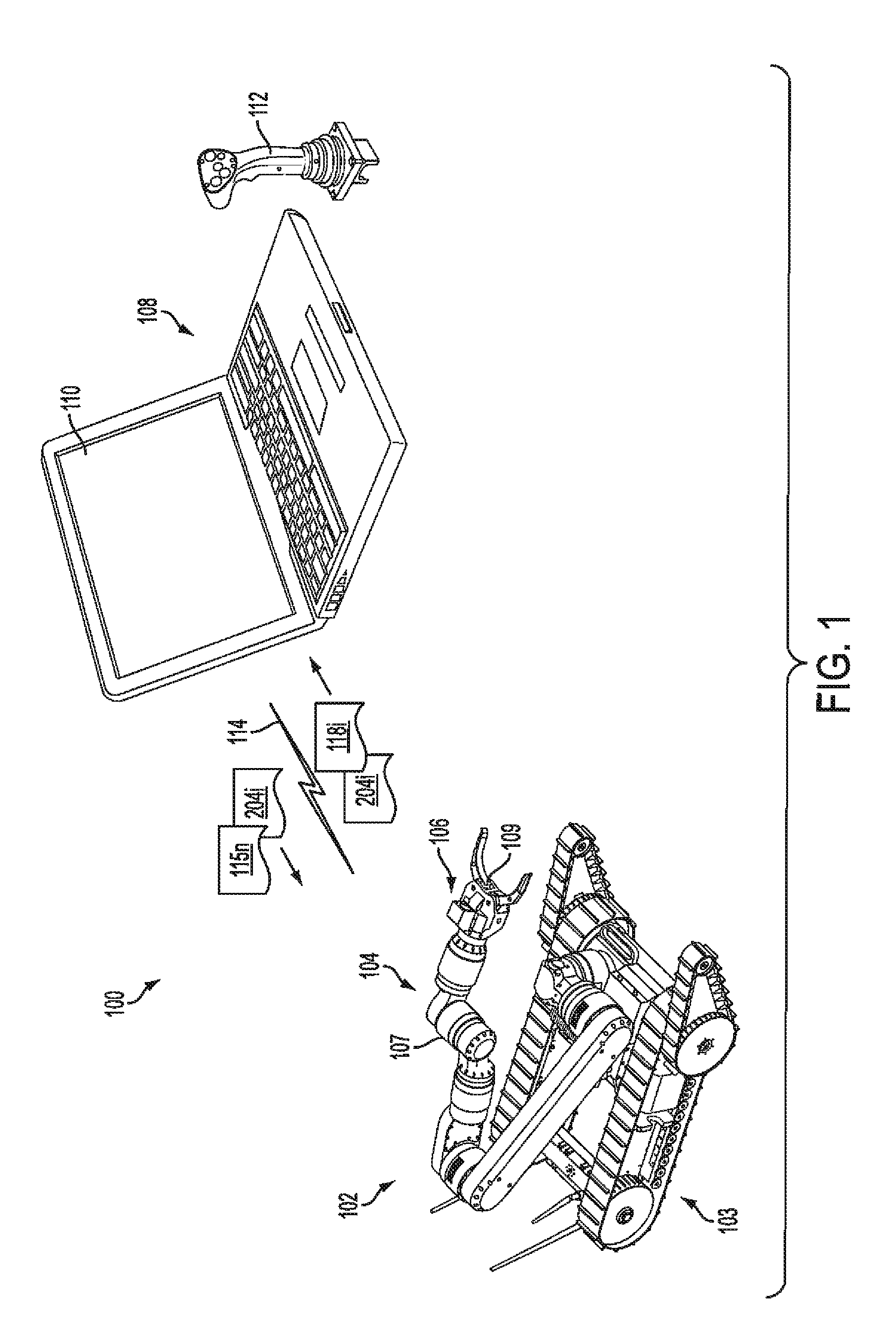
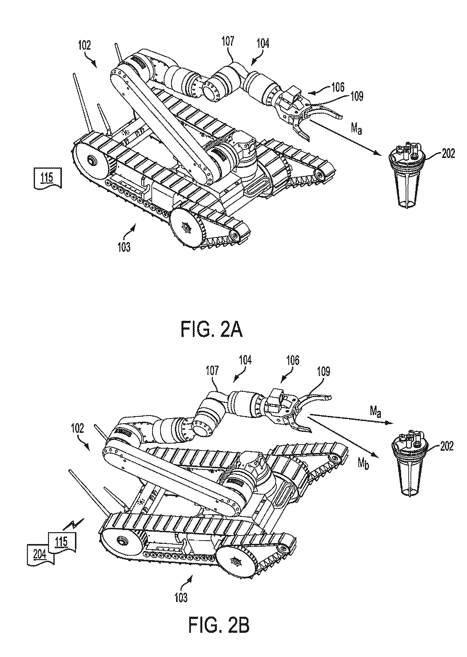
[0021]In order to ensure proper control of a robotic system, a control operator is often provided wit...


PUM


Abstract

Robotic system (100) includes a processing device (512) and a plurality of robot actuators (501) to cause a specified motion of the robot (102). The processing device (512) responds to one or more user robot commands (115) initiated by a control operator input at a remote control console (108). A user robot command will specify a first movement of the robot from a first position to a second position. The processing device will compare a current pose of the robot to an earlier pose of the robot to determine a difference between the current pose and the earlier pose. Based on this comparing, the processing device will selectively transform the user robot command to a latency-corrected robot command which specifies a second movement for the robot which is different from the first movement.

Description

BACKGROUND OF THE INVENTION[0001]1. Statement of the Technical Field[0002]The inventive arrangements relate to teleoperation systems, and more particularly to teleoperation systems that operate in a high latency environment.[0003]2. Description of the Related Art[0004]Teleoperation involves the manipulation and control of objects and devices over long distances. A teleoperation system usually includes an unmanned robotic system and a user control console. A data link facilitates communications between the control console and the unmanned robotic system so that user commands can be provided to the unmanned robotic system which is usually located some distance away. Most unmanned robotic systems are controlled over a wireless link. Unmanned remotely controlled systems include unmanned aerial vehicles (UAV), unmanned ground vehicles (UGV), unmanned underwater vehicles (UUV) and robotic manipulators. An unmanned remotely controlled system as described herein can sometimes include a mova...

Claims


Application Information

Patent Timeline
Patent Type & Authority Patents(United States)
IPC IPC(8): B25J9/16
CPCB25J9/1692B25J9/1689G05B2219/40147G05B2219/40149G05B2219/40151G05B2219/40174Y10S901/02G05D1/0022
Inventor SUMMER, MATTHEW D.BOSSCHER, PAUL M.SUMMER, MICHAEL J.ORTEGA-MORALES, MIGUEL
Owner HARRIS CORP
Why Eureka
Try Eureka