
Apparatus and optical method of ranging and of high bit-rate communication

a technology of optical communication and antenna, applied in the field of antenna and optical communication, can solve the problems of limiting the distance that can be achieved, the frequency of repetition of pulses (or the rate) being limited by the constraints of ocular safety, and the inability to detect echoes during the transmission of pulses

Active Publication Date: 2015-09-29
THALES SA
View PDF13 Cites 21 Cited by
  • Summary
  • Abstract
  • Description
  • Claims
  • Application Information

AI Technical Summary

Benefits of technology

The patent describes an apparatus that can perform both long-range ranging and high-bit-rate optical communication with a single device. It is designed to be flexible and can quickly transition between the two modes. This means that the apparatus can switch between long-range ranging and high-bit-rate communication without needing to switch devices.

Problems solved by technology

To increase the ranging distance despite these atmospheric losses, the following ways are possible:increasing the energy per pulse, but this increase is limited by the constraints of ocular safety and by the volume of the transmitter which increases with the energy per pulse,increasing the dimension of the receiving pupil but this increases the dimensions of the system,increasing the sensitivity of the receiver with multipulse systems using micro-lasers or fiber optic lasers.
Detection of the echoes is not possible during the transmission of the pulses.
But in the case of post-integration, the frequency of repetition of the pulses (or rate) limits the distance that can be achieved because of the ambiguity concerning the distance.
Such apparatus are then bulky and heavy.

Method used


Image

  • Apparatus and optical method of ranging and of high bit-rate communication
  • Apparatus and optical method of ranging and of high bit-rate communication
  • Apparatus and optical method of ranging and of high bit-rate communication

Examples


Embodiment Construction

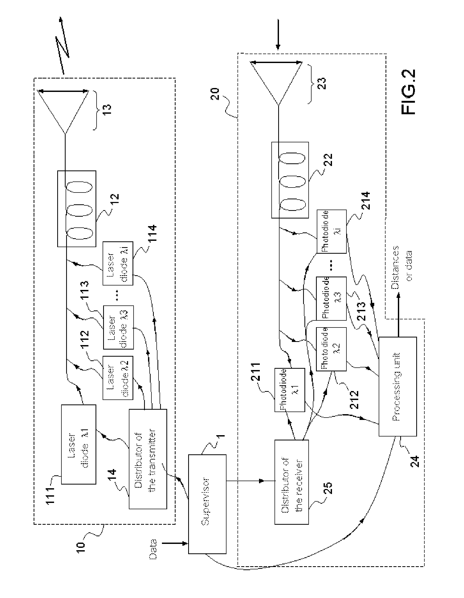
[0043]The optical apparatus for ranging and communication can be monowavelength or multiwavelength.

[0044]Consideration is given first of all to a monowavelength apparatus.

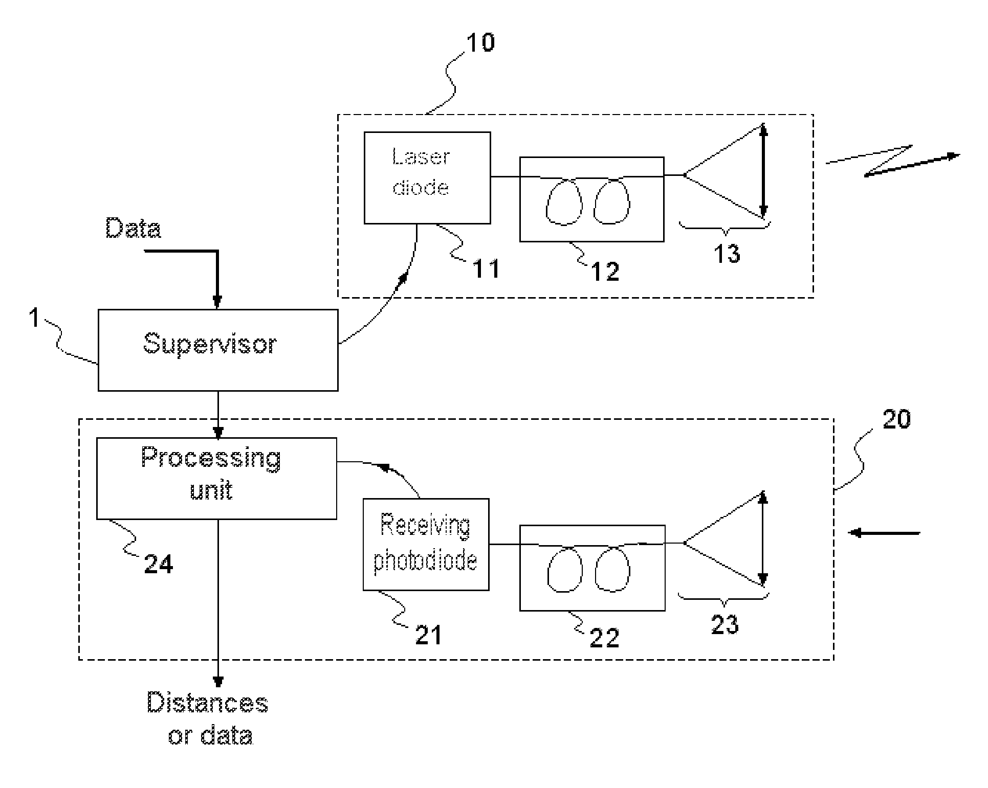
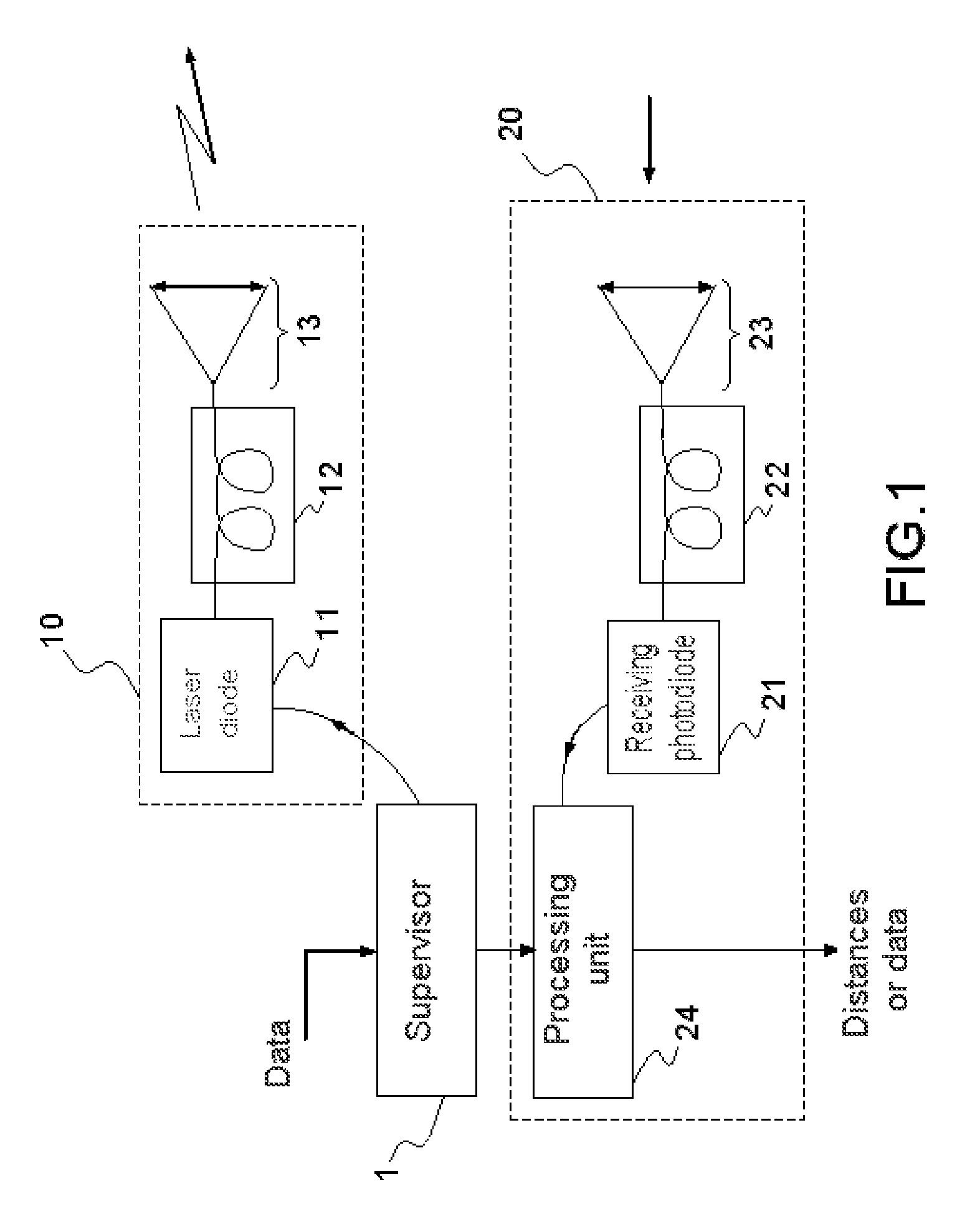
[0045]With reference to FIG. 1, a transmitting device 10 that is common to the rangefinder and to the communication system will be described. It comprises a laser source 11 that can be connected at the output to an amplifier 12 such as a fiber amplifier.

[0046]First, the case of a laser diode transmitter that is not connected at the output to an amplifier is envisaged.

[0047]The laser diode transmitter can be a single-ribbon laser diode or a stack of single-ribbon diodes transmitting collectively.

[0048]The pulse width is produced by the power supply of the laser diode or by that of the stack. Beyond a threshold, the transmission power is proportional to the power supply current.

[0049]In virtually continuous operation for communication, the maximum current and therefore the mean power are mainly limited by the thermal...


PUM


Abstract

An optical apparatus for ranging and communication in free space comprises a rangefinder comprising a device for transmitting an optical signal to a target and a device for receiving the signals backscattered by the target. A system for optical communication in free space comprises a device for transmitting an optical signal to a remote optical receiving device. The transmitting device of the rangefinder and transmitting device of the communication system is a transmitting device common to the rangefinder and communication system and transmitting pulses of peak power greater than 50 W and shape factor less than 0.01 or a modulated continuous signal of peak power less than 10 W and shape factor equal to approximately 0.5 and the apparatus comprises a supervisor controlling the common transmitting device according to two modes, the pulse mode to perform the ranging function, or the modulated continuous mode to perform the optical communication function.

Description

CROSS-REFERENCE TO RELATED APPLICATIONS[0001]This application is a National Stage of International patent application PCT / EP2011 / 070428, filed on Nov. 18, 2011, which claims priority to foreign French patent application No. FR 1004817, filed on Dec. 10, 2010, the disclosures of which are incorporated by reference in their entirety.FIELD OF THE INVENTION[0002]The field of the invention is that of apparatus performing the functions of optical ranging and of optical communication in free space. More specifically, it involves an apparatus of which the range of the airborne rangefinder in air-air can reach up to several tens of kilometers and performing communications in free space at very high bit rate, of the order of several gigahertz.BACKGROUND[0003]A rangefinder is used to measure the distance separating it from a target. An optical rangefinder uses the propagation of the light as a measurement means. It comprises a transmitter and a receiver. It transmits light toward the target an...

Claims


Application Information

Patent Timeline
IPC IPC(8): G01C3/08G01S17/74H04B10/112G01S7/483G01S7/486G01S17/10G01S17/86
CPCG01C3/08G01S7/483G01S17/74H04B10/112G01S17/10G01S7/4815G01S7/484G01S7/486G01S7/006G01S17/86G01S17/88G01S17/02G01S7/481
Inventor ROUSSEAU, PASCAL
Owner THALES SA
Learn More