Threshing mechanism with swivellable concaves

a thresher and concave technology, applied in the field of threshers, can solve the problems of unfavorable crop flow and threshing process quality, second thresher follows a non-uniform course, and unfavorable crop flow, and achieves the effect of simplifying the handling of replaceable concave segments

Active Publication Date: 2015-10-06
CLAAS SELBSTFAHRENDE ERNTEMASCHINEN GMBH
View PDF15 Cites 18 Cited by
  • Summary
  • Abstract
  • Description
  • Claims
  • Application Information

AI Technical Summary

Benefits of technology

[0006]To that end, the present invention provides a threshing mechanism of the initially mentioned type characterized by higher threshing quality and improved crop flow for different crop types.
[0024]The specific embodiment and arrangement of the plate on the main body makes it possible to position the grate such that the crop-processing device does not act on the crop when in a first position. In a second position of the crop-processing device, the grate is swivelled so far that the smooth leg forms a typo of ramp and, therefore the gap width between the second section of the first concave and the second threshing drum decreases, wherein the gap width between the concaves and the threshing drums remains unchanged. Such construction or arrangement results in a more aggressive threshing behavior. In a third position of the crop-processing device designed as a grate, the circular arc-shaped projections act on the crop making it possible to obtain a markedly more aggressive behavior during disawning.

Problems solved by technology

This means that the gap profile from the inlet gap between the first concave and the second threshing drum to the outlet gap between the second concave and the second threshing drum follows a non-uniform, bulged course.
This arrangement has an unfavorable effect on the crop flow and the quality of the threshing process.

Method used


Image

  • Threshing mechanism with swivellable concaves
  • Threshing mechanism with swivellable concaves
  • Threshing mechanism with swivellable concaves

Examples


Embodiment Construction

[0035]The following is a detailed description of example embodiments of the invention depicted in the accompanying drawings. The example embodiments are presented in such detail as to clearly communicate the invention and are designed to make such embodiments obvious to a person of ordinary skill in the art. However, the amount of detail offered is not intended to limit the anticipated variations of embodiments; on the contrary, the intention is to cover all modifications, equivalents, and alternatives falling within the spirit and scope of the present invention, as defined by the appended claims.

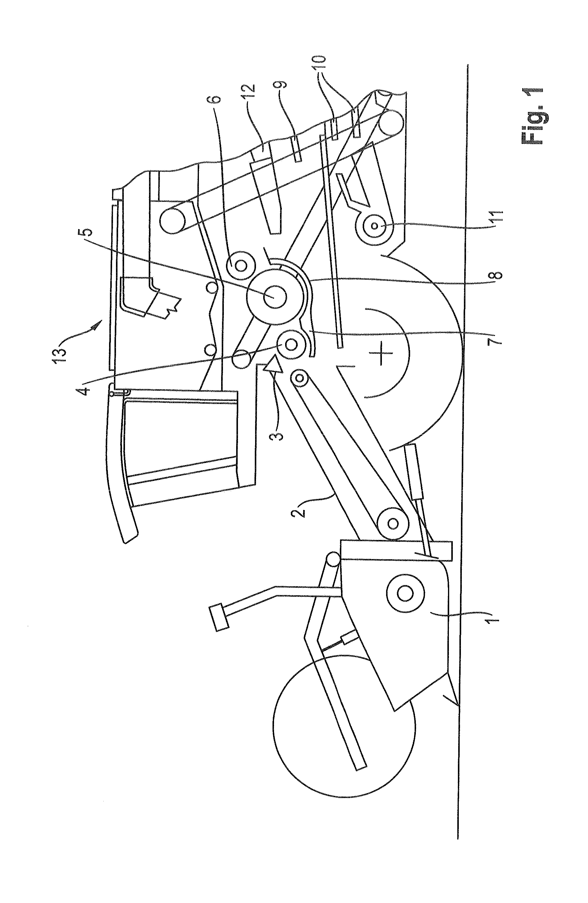
[0036]FIG. 1 presents, in a schematic depiction, a partial view of a self-propelled combine harvester 13. Combine harvester 13 is equipped, in the front region thereof, with a header 1 comprising a reel and a feed rake 2 adjoining this header. In the harvesting operation, the crop lying on the field, which can be grain or another stalked crop, is cut by a cutting mechanism disposed within t...


PUM


Abstract

A threshing mechanism is formed with a first threshing drum and a second threshing drum disposed one behind the other in a direction of crop flow. A first concave encloses the first threshing drum and the second threshing drum in sections in a circumferential direction. A second concave encloses the second threshing drum in sections in the circumferential direction. The concaves are displaceable in a radial direction of the threshing drums and are formed with at least one crop-processing device disposed at the first concave. The first concave and the second concave are swivellable about a common axis connecting the concaves. The enclosure of the second threshing drum by the first concave and the second concave is approximately identical.

Description

CROSS-REFERENCE TO A RELATED APPLICATION[0001]The invention described and claimed hereinbelow is also described in German Priority Document DE 10 2013 100057.6, filed on Jan. 4, 2013. The German Priority Document, the subject matter of which is incorporated herein by reference, provides the basis for a claim of priority of invention under 35 U.S.C. 119(a)-(d).BACKGROUND OF THE INVENTION[0002]The invention relates to a threshing mechanism comprising first and second threshing drums disposed one behind the other, a first concave enclosing the first threshing drum and the second threshing drum in sections in the circumferential direction and, a second concave enclosing the second threshing drum in sections in the circumferential direction. The concaves are displaceable in the radial direction of the threshing drums and at least one crop-processing device is disposed at the first concave.[0003]A threshing mechanism of the initially described type is known from EP 0 745 317 A1. EP 0 745 ...

Claims


Application Information

Patent Timeline
Patent Type & Authority Patents(United States)
IPC IPC(8): A01F12/28A01F12/26
CPCA01F12/28A01F12/26
Inventor HOLTMANN, BERNDESKEN, DIRKKRIEFT, MANFREDBUDDENKOTTE, FRANZBUSSMANN, RALF
Owner CLAAS SELBSTFAHRENDE ERNTEMASCHINEN GMBH
Why Eureka
Try Eureka