
Methods and systems for directing remote aerial refueling operations

Active Publication Date: 2015-10-06
THE BOEING CO
View PDF13 Cites 14 Cited by
  • Summary
  • Abstract
  • Description
  • Claims
  • Application Information

AI Technical Summary

Benefits of technology

The patent describes a method for helping to see and refuel planes in the air. It suggests adding a video overlay to show the position of the refueling boom and the tanker aircraft, with guidance to help align and couple them up. This can make the process easier and safer for both airplanes.

Problems solved by technology

As can be easily understood, the currently utilized boom operation methodology involves many steps to be accomplished manually by the boom operator, with little or no automation to aid in this critical and sensitive operation.
Another limitation is that the currently implemented boom operation methodology requires a qualified full time boom operator, adding expense to the mission and putting another aircrew member at risk.
In addition, current systems do not do employ automated positive target identification which can result in having to manually establish communication between the tanker and the receiving aircraft.
Manual identification can be distracting for the crew and can defocus the refueling effort, which is an inherently dangerous operation and requires the utmost of concentration to accomplish.
Further, in certain emission controlled (EMCON) situations, radio communications with the receiver are not possible, thus making positive receiver identification more difficult.
There is no capability to give target identification and other visual aim point cues to the boom operator to accurately position the boom relative to the receiver aircraft as the mission unfolds.
Further, there are no visual cues identifying the location and hazards surrounding the refueling receptacle, such as a Universal Aerial Refueling Receptacle Slipway Installation (UARRSI), on the receiving aircraft.
As can be easily understood, the lack of cues and manually intensive effort extended by boom operators can result in significant operator stress and fatigue.

Method used


Image

  • Methods and systems for directing remote aerial refueling operations
  • Methods and systems for directing remote aerial refueling operations
  • Methods and systems for directing remote aerial refueling operations

Examples


Embodiment Construction

[0026]The embodiments described herein are related to methods and systems to enhance the aerial refueling boom guidance on a tanker aircraft eventually leading to autonomous operations including refueling UAVs.

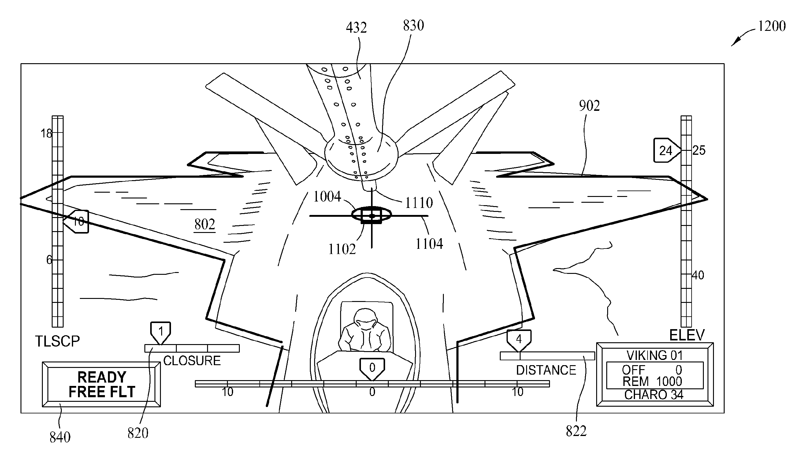
[0027]The advent of the Aerial Refueling Operator Station (AROS) as mentioned above allows for the exploitation of new technology. In the embodiments described herein, the boom operator is provided with new tools to enable them to increase the efficiency and safety within which to perform their mission. Specifically, the described embodiments are related to a leveraging of the technologies resident in a modern AROS is to provide the boom operator with overlaid guidance on top of their visual image of the refueling environment. Such guidance projects the contact point where the boom engages the receiver aircraft and helps the boom operator fly the boom to the correct location, and then extend the boom to complete the contact with the receiver aircraft. As such, the state of the...


PUM


Abstract

A method for aerial refueling situational awareness is described. The method includes providing, to a display, a video image of the refueling environment, and providing at least one video overlay onto the video image, the at least one video overlay indicative of a positional relationship between an aircraft to be refueled and a tanker aircraft, the at least one video overlay including at least one guidance cue to assist in the alignment and coupling of the aerial refueling boom with the receiving aircraft receptacle.

Description

BACKGROUND[0001]The field of the disclosure relates generally to aerial refueling, and more specifically, to methods and systems for directing remote aerial refueling operations.[0002]As newer aerial refueling tankers are fielded, the boom operator is being moved from looking out a window in the tail of the aircraft to a highly sophisticated remote workstation near the flight deck. This move requires a high-fidelity enhanced vision system to be provided to the boom operator to enable them to visually acquire the aerial refueling environment, so that they may manually “fly” the aerial refueling boom into the receiver aircraft's refueling receptacle. This remote workstation is sometimes referred to as the Aerial Refueling Operator Station (AROS).[0003]Both the AROS and the older systems in which the boom operator is in the tail of the aircraft utilize manual (human initiated) acquisition and identification of the receiving aircraft. Generally, acquisition is made via handoff from the ...

Claims


Application Information

Patent Timeline
IPC IPC(8): B64D39/00
CPCB64D39/00
Inventor BRAY, JAMES F.COBLEIGH, KENNETH A.
Owner THE BOEING CO
Learn More