Lighting device having a smooth cut-off

a lighting device and cut-off technology, applied in the direction of semiconductor devices for light sources, light and heating apparatus, planar light sources, etc., can solve the problems of unsatisfactory control of the limits of the region to be illuminated, unnatural light near the cut-off direction, and unpleasant lighting effects. , to achieve the effect of limiting light loss and optimizing control of the size and shape of the area

Active Publication Date: 2015-10-06
KONINK PHILIPS ELECTRONICS NV
View PDF19 Cites 2 Cited by
  • Summary
  • Abstract
  • Description
  • Claims
  • Application Information

AI Technical Summary

Benefits of technology

[0009]A purpose of the invention is to smooth the light cut-off region in the area to illuminate, created by said edge of the reflector, while optimizing the control over the size and shape of the area to be illuminated and limiting the light losses.

Problems solved by technology

Problems encountered with such reflectors are the contrast of the light that is sometimes too high at the limit or edge of the region to illuminate and / or the light is not uniform near the cut-off direction, especially when a plurality of punctual light sources is used.
As a consequence the lighting effects may be unpleasant and / or non aesthetic, especially problematic for Accent Lighting or Spot Lighting applications.
However, the limits of the region to be illuminated may be not sufficiently controlled when using this technique and the lighting efficiency may be not optimized.

Method used


Image

  • Lighting device having a smooth cut-off
  • Lighting device having a smooth cut-off
  • Lighting device having a smooth cut-off

Examples


Embodiment Construction

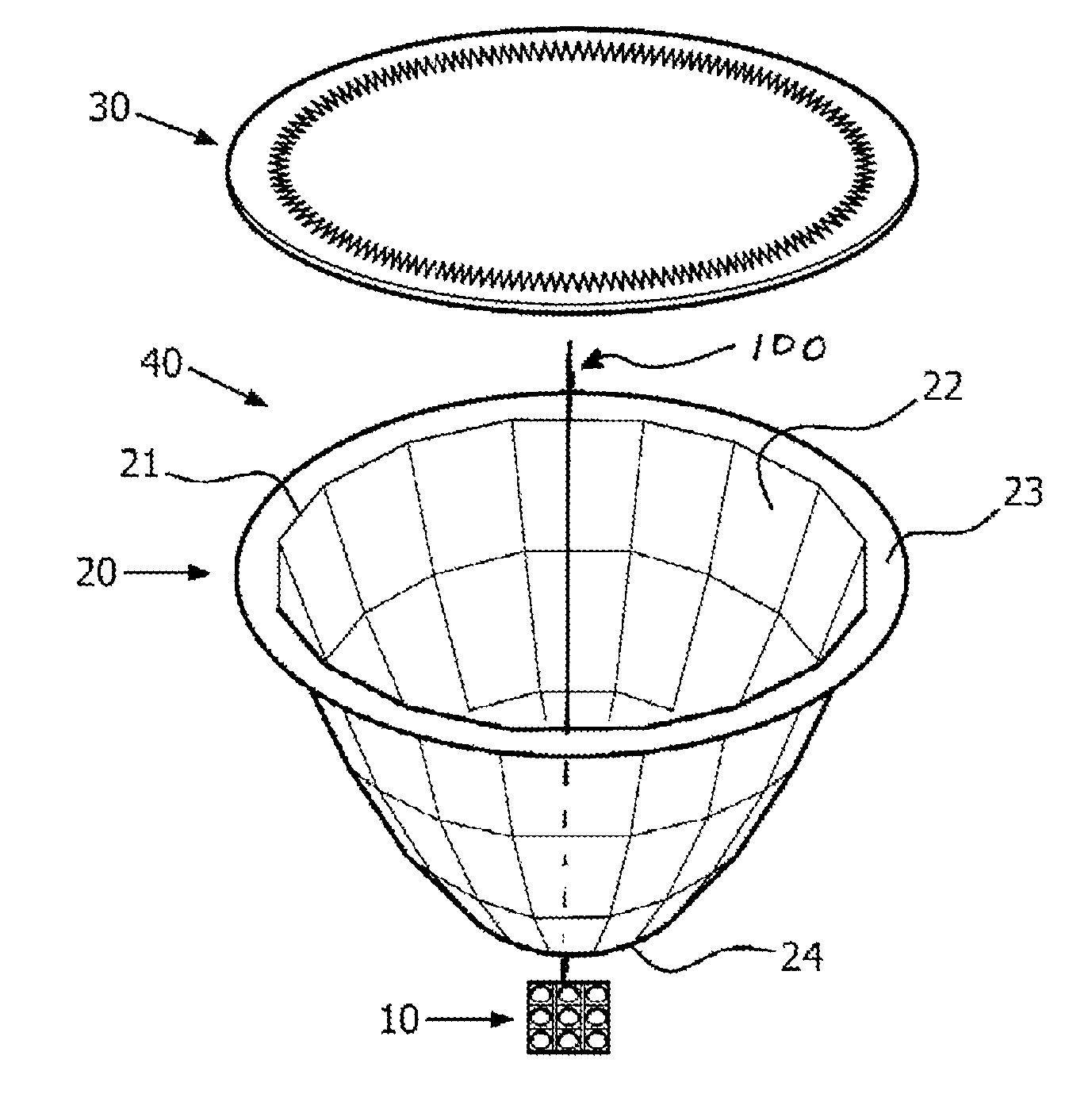
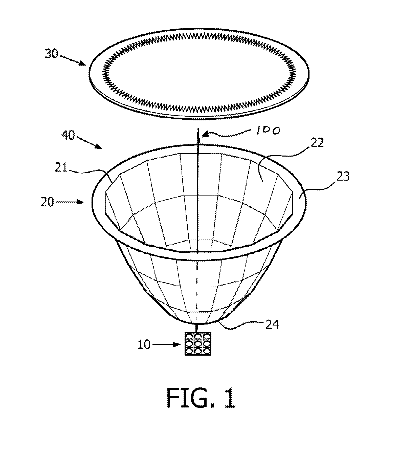
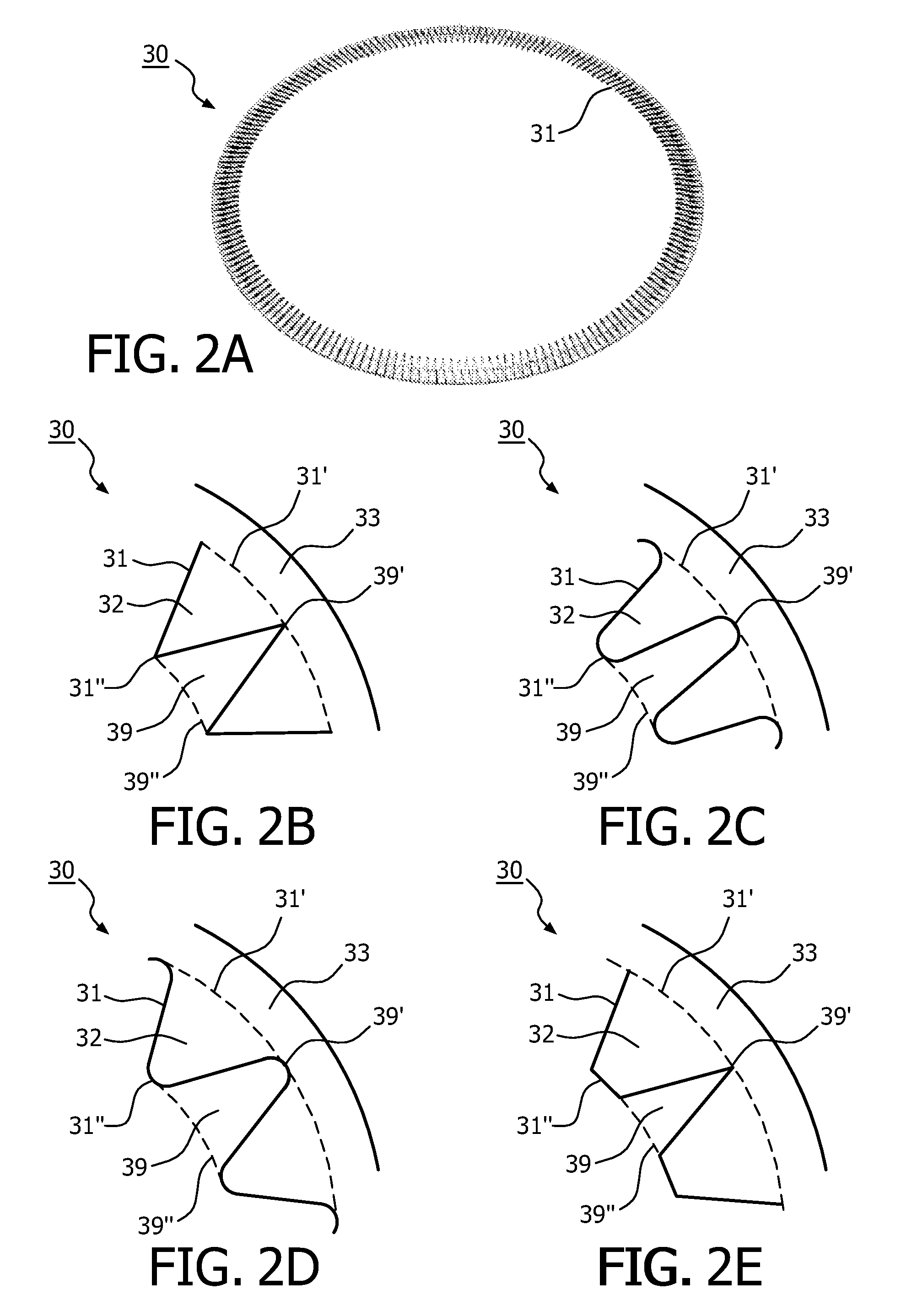
[0056]FIG. 1 shows a light device 40 according to the invention comprising:[0057]a light source assembly 10;[0058]a reflector 20 comprising a reflective surface 22 and a first edge 21;[0059]a light-modifying member 30 adapted to modify lighting feature(s) of light rays.

[0060]The light source assembly 10 may comprise one or a plurality of light source(s). The plurality of light sources may extend over a line, a plane or a volume. A light source may be any kind of light source, such as an incandescent lamp, halogen lamp, a high-intensity discharge (so-called HID) lamp or a light-emitting diode (LED). The light source assembly 10 may comprise a unique or a plurality of support(s) of the light source(s) provided with electrical and / or electronic path to a current supply and optionally to a light controller. The circuit board may comprise this lighting controller. A heat sink or nay other cooling system may be provided beneath the LEDs or the circuit board, to dissipate the heat from the...


PUM


Abstract

The invention relates to a lighting device comprising: —at least one light source (11); —a reflective member (20) comprising a reflective surface (22) and an edge (21) (“first edge”) forming a light cut-off of light rays passing in a region adjacent to this first edge (21); —a light-modifying member (30) adapted to modify lighting feature(s) of light rays and having an edge (“second edge”). The light-modifying member (30) extends from the reflective member (20) to this second edge (31) over a surface area defined to receive a part of the light rays passing in said region. The second edge is designed such that, among said part of light rays, the light-modifying member (30) modifies proportionally more light rays passing proximate the first edge than light rays passing less proximate the first edge (21). The invention relates also to said light-modifying member (30) per se.

Description

TECHNICAL FIELD[0001]The invention relates to a luminaire or a lighting device comprising:[0002]at least one light source, such as one or several LEDs;[0003]a reflector (or reflective member) comprising a reflective surface and a first edge, the first edge forming a light cut-off of light rays passing proximate this first edge—the first edge defines typically the light outlet of the reflector.[0004]The light source(s) is usually located within the reflector, the reflector being arranged to reflect the light emitted by the light source(s) in order to direct the emitted rays into specific directions to illuminate a region area limited by said light cut-off.BACKGROUND OF THE INVENTION[0005]Problems encountered with such reflectors are the contrast of the light that is sometimes too high at the limit or edge of the region to illuminate and / or the light is not uniform near the cut-off direction, especially when a plurality of punctual light sources is used. As a consequence the lighting ...

Claims


Application Information

Patent Timeline
Patent Type & Authority Patents(United States)
IPC IPC(8): F21V1/12F21V3/04F21V13/04F21V13/10F21V11/00F21V7/04F21V7/06F21Y101/02F21Y105/00
CPCF21V13/04F21V3/04F21V13/10F21V7/048F21V7/06F21V11/00F21Y2101/02F21Y2105/001F21Y2105/10F21Y2115/10
Inventor JOUFFRIEAU, MATTHIASFOURNIER, DENIS
Owner KONINK PHILIPS ELECTRONICS NV
Why Eureka
Try Eureka