

Laser thickness gauge and method including passline angle correction
Patent Information
- Authority / Receiving Office
- US · United States
- Patent Type
- Patents(United States)
- Current Assignee / Owner
- ADVANCED GAUGING TECH
- Publication Date
- 2015-10-06
Smart Images
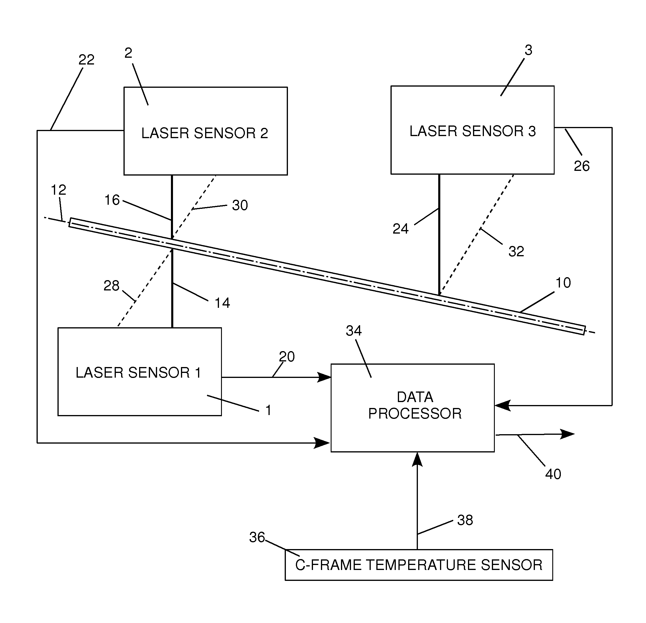
Figure 1 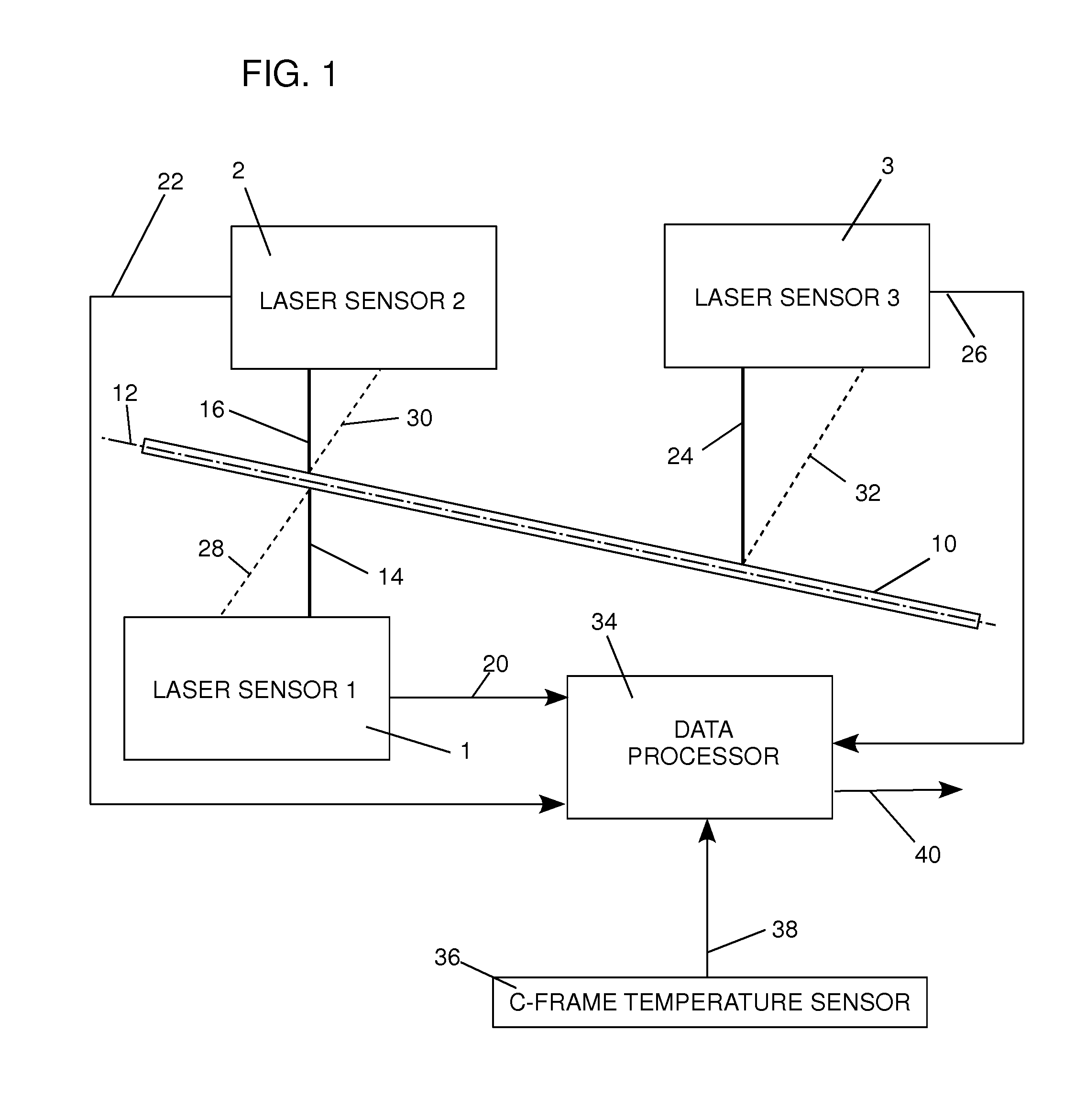
Figure 2 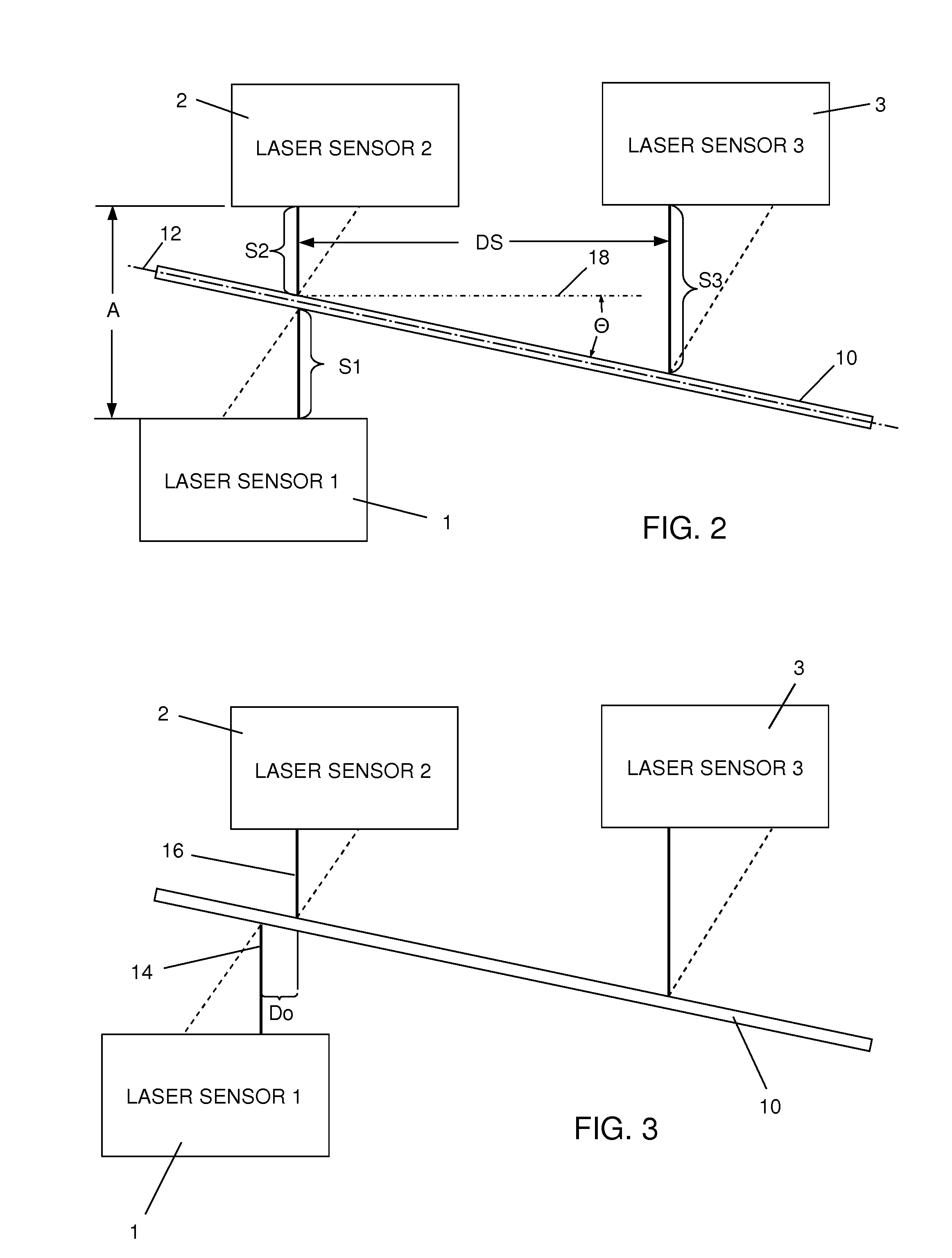
Figure 3
Abstract
Description
CROSS-REFERENCES TO RELATED APPLICATIONS
[0001] (Not Applicable)STATEMENT REGARDING FEDERALLY-SPONSORED RESEARCH AND DEVELOPMENT
[0002] (Not Applicable)THE NAMES OF THE PARTIES TO A JOINT RESEARCH AGREEMENT
[0003] (Not Applicable)REFERENCE TO AN APPENDIX
[0004] (Not Applicable)FIELD OF THE INVENTION
[0005] The invention is an industrial measurement device and associated method that measure in real time the thickness of any web of a flat material, such as in strip, sheet or coil form, while the web is being processed. More particularly, the invention uses laser beams from at least three laser sensors and measures the web thickness even when the web is oriented along a web passline that is oblique; that is, not perpendicular to the three laser beams of the sensors. Embodiments of the invention can also be calibrated to correct measurement errors resulting from misalignment of the laser beams, temperature variations and additional unknown errors that are inherent in any practical thickness gauge...