Motion sickness reduction

a technology of motion sickness and reduction, applied in the field of motion sickness reduction, can solve the problems of motion sickness, contribute to motion sickness in the occupant, and people may get motion sickness, so as to reduce the likelihood of motion sickness, and optimize the effect of the devi

Inactive Publication Date: 2015-10-06
KIM SAMUEL
View PDF34 Cites 10 Cited by
  • Summary
  • Abstract
  • Description
  • Claims
  • Application Information

AI Technical Summary

Benefits of technology

[0015]The inventor has recognized that there is a need for an improved device capable of presenting visual stimuli to an observer in order to reduce a likelihood that the observer will experience motion sickness. The inventor has further recognized that it is advantageous to have a device capable of automatically adjusting to observer activities and environmental conditions in order to improve and / or optimize the effectiveness of the device in reducing the likelihood of motion sickness. Having made the foregoing discoveries and conclusions, the inventor has invented a device and method for reducing motion sickness and a method of adjusting a motion sickness reduction device including, among others, moving an image presentation device in relation to a viewer; and adjusting an image on said image presentation device to reduce a motion sickness response of said viewer.

Problems solved by technology

People may get motion sickness when their brains receive conflicting messages.
These motions can contribute to motion sickness in an occupant.
These conflicting signals can lead to motion sickness.
A greater rocking motion of the ship will increase the disparity between what the passenger feels and what he sees, and so ships in heavy storms often have many passengers suffering from motion sickness.
Symptoms may alleviate when the motion stops; however, it has been found that for some people it can take a significant period of time for symptoms to subside.
The downside of using any of these medications includes cost, inconvenience, and potential side effects.
It has been found however, that such devices have limited success in preventing motion sickness.

Method used


Image

  • Motion sickness reduction
  • Motion sickness reduction
  • Motion sickness reduction

Examples


Embodiment Construction

[0052]The inventor has discovered that a risk of motion sickness, and the severity of motion sickness experienced, can be reduced by providing visual stimuli to the occupant of a dynamic environment such as a moving vehicle. With this in mind, the inventor has invented the various systems, devices and methods described and claimed in this application. Among these are the described embodiments including a video camera adapted to capture a dynamic image of a surrounding environment and a video display screen coupled to a moving vehicle and positioned for viewing by an occupant of the vehicle. The invention includes methods and apparatus to improve the character and effectiveness of the motion sickness reduction device by adjusting and controlling various aspects of the visual stimuli presented to the occupant.

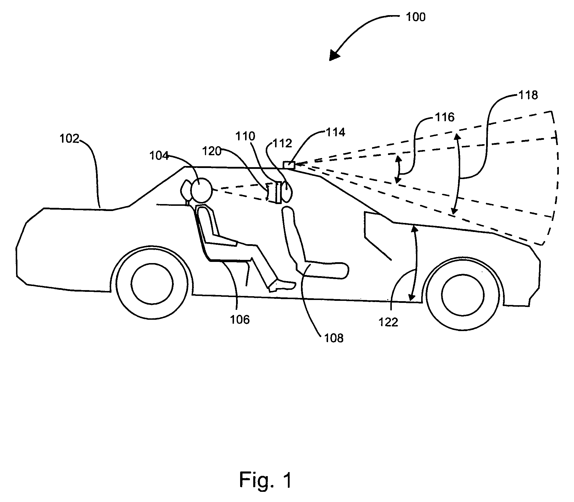
[0053]FIG. 1 shows an exemplary vehicle including a motion sickness reduction device 100 according to one embodiment of the invention. In other exemplary embodiments the occupant...


PUM


Abstract

A motion sickness reduction device includes an image capture device for capturing an image device environment and an image display device for displaying image related to the captured image. In order to effectively prevent or reduce motion sickness, the right amount of motion must be displayed on the image display device when the vehicle accelerates or turns. Various methods are disclosed for adjusting the image on the display device and / or the angle of the environment subtended to make the motion sickness reduction device effective.

Description

CROSS-REFERENCE TO RELATED APPLICATIONS[0001]The present application is a continuation of PCT patent application number PCT / US 2007 / 020068, having an international filing date of Sep. 13, 2007, which claims priority to U.S. provisional patent applications No. 60 / 844,424, filed on Sep. 13, 2006 and 60 / 851,984 filed on Oct. 16, 2006, the disclosures of which are herewith incorporated by reference in their entirety, and the benefit of which is herewith claimed. The present application also is a continuation-in-part of co-pending U.S. non-provisional patent application Ser. No. 11 / 166,483 having a filing date of Jun. 24, 2005 now U.S. Pat. No. 7,722,526, which claims the benefit of U.S. provisional patent application No. 60 / 588,710 filed on Jul. 16, 2004 and U.S. provisional patent application No. 60 / 630,055, filed on Nov. 22, 2004.FIELD OF THE INVENTION[0002]The present invention relates to motion sickness reduction and more particularly to devices and methods for employing visual stim...

Claims


Application Information

Patent Timeline
Patent Type & Authority Patents(United States)
IPC IPC(8): H04N7/18G06F3/01G06T3/40A61M21/02A61M21/00G09G5/00
CPCG06T3/40A61M21/02G06F3/011A61M2021/005G16H20/70G16H40/63
Inventor KIM, SAMUEL
Owner KIM SAMUEL
Why Eureka
Try Eureka