Oven provided with aperture for air entry into its cavity

a technology of oven cavity and aperture, which is applied in the field of oven, can solve the problems of preventing the user from rapid cleaning of the oven, preventing the user from removing the oven cavity quickly, and affecting the cooking effect of food placed in the oven cavity

Active Publication Date: 2015-10-13
WHIRLPOOL CORP
View PDF62 Cites 17 Cited by
  • Summary
  • Abstract
  • Description
  • Claims
  • Application Information

AI Technical Summary

Benefits of technology

[0011]An object of the present invention is to provide an oven which is improved compared with known ovens.
[0012]A particular object of the invention is to provide an oven which enables a food contained within its cavity to be browned or surface finished while at the same time not involving or considerably limiting any continuation of oven cooking of the food by heat convection, but utilizing to its maximum effect the irradiation of the heating means present within the cavity.
[0013]Another object is to provide an oven of the aforestated type in which the cavity can be cooled within a very short time, which is in any event less than that of known ovens.

Problems solved by technology

A drawback of known cooking methods is that a food placed in the oven cavity can exceed the point of optimum internal cooking, reached on termination of the cooking process, if it remains in the closed cavity after deactivation of the heating elements present therein.
Moreover, after removal of the food from the oven cavity, this latter remains hot for a considerable time period.
This condition prevents rapid cleaning of the oven by the user.
The condition also delays use of the oven for preparing another food if this requires cooking temperatures less than those used in the previous cooking / cleaning process.
There is also the problem that if the oven has been switched off but its cavity and closure door are still hot, persons, in particular children, can suffer burns if they come into contact with it even several minutes after switch-off.
Such ovens do not enable fresh air to be withdrawn and fed into the oven, i.e. taken directly from the environment outside the oven, as the air flow flows only towards the outside of the cavity (normally entrained by the venturi effect); this flow is in the form of air which is not fresh as it has already been used to cool the cabinet.

Method used


Image

  • Oven provided with aperture for air entry into its cavity
  • Oven provided with aperture for air entry into its cavity

Examples


Embodiment Construction

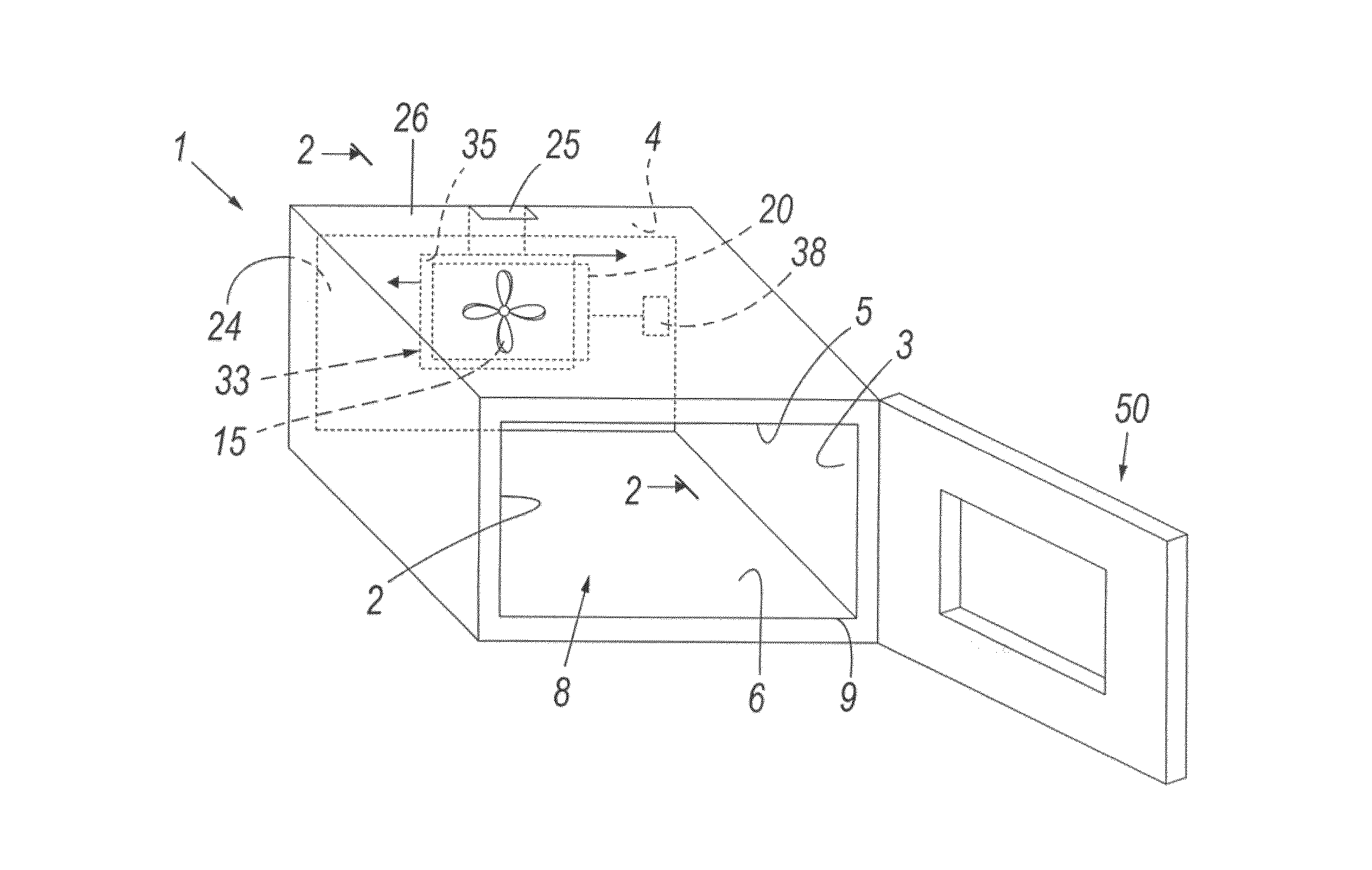
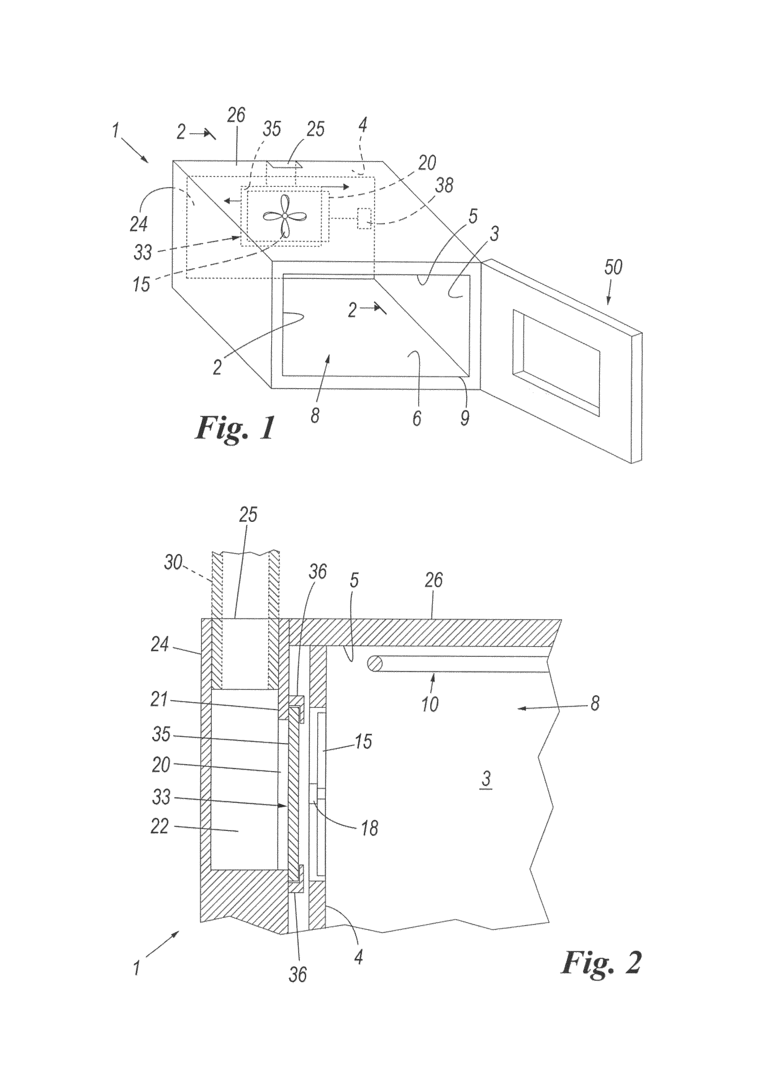
[0023]With reference to the the figures, an oven comprises a housing or structure 1 presenting side walls 2, 3, a rear wall 4, an upper wall 5 and a lower wall 6. These walls define and bound a cavity 8 open at 9 where a door 50 is present to close the cavity 8. The oven comprises usual heating elements 10 of which only one, the upper element, is visible in FIG. 1; for simplicity, this heating element 10, usually defined by an electrical resistance element, is shown in proximity to the upper wall 5 of the cavity 8.

[0024]The oven also comprises a cooling fan for the cabinet in which the oven is inserted.

[0025]According to the invention, to improve oven performance and to enable it to quickly cool down after use, at least one aperture 20 is provided in at least one wall (the rear wall 4 in the example) and is connectable selectively (i.e. interruptably and preferably such as to vary its opening cross-section) to the environment external to the oven so as to be able to at least introdu...


PUM


Abstract

An oven comprises a housing or structure presenting a plurality of inner walls and outer walls, the inner walls defining an oven cavity in which means are provided for cooking foods, the means comprising a grill for browning the foods, the oven also comprising a door for closing the cavity. At least one aperture is present in at least one of the walls of the oven cavity, or in the door, for selective connection to the environment external to the oven, such as to interceptably introduce fresh ambient air into the cavity, controllable interceptor means being provided at the aperture to enable this selectivity in introducing the ambient air into the cavity.

Description

BACKGROUND OF THE INVENTION[0001]1. Field of the Invention[0002]The present invention relates to an oven in accordance with the introduction to the main claim.[0003]The heating elements positioned in the oven cavity tend to heat both the cavity walls and each item positioned therein by heat transfer by natural convection, by forced convection using a cooking fan, or by irradiation. Heat convection is by heat transfer from the heating elements and from the heated physical parts of the oven to the air present within the oven cavity, and optionally by the operation of a cooking fan. Heat irradiation is by the infrared radiation emitted by the heating surfaces and heated surfaces towards the cooler surfaces, for example those of the food.[0004]The cabinet in which the oven is installed is cooled by a cabinet cooling fan, external to the cavity.[0005]That heat portion transferred by irradiation is more effective for food browning or grilling than that due to convection. In particular, ir...

Claims


Application Information

Patent Timeline
Patent Type & Authority Patents(United States)
IPC IPC(8): A21B3/02F24C15/00A21B1/26F24C15/20F24C15/02A21B3/04F24C15/32
CPCF24C15/006F24C15/2007A21B1/26F24C15/322
Inventor DISTASO, TAMARADOYLE, JOHNVENEZIA, MICHELEGIULIANI, MARCOMAZZETTI, CRISTINA
Owner WHIRLPOOL CORP
Why Eureka
Try Eureka