
Method for producing honeycomb structure

a honeycomb and structure technology, applied in the field of honeycomb structure production, can solve the problems of insufficient consideration of how the temperature does not easily drop near, and the cooling of the honeycomb formed body takes a long period of time, so as to improve the productivity of the honeycomb structure, reduce the amount of coolant used, and increase the utilization efficiency of coolant.

Active Publication Date: 2022-04-05
NGK INSULATORS LTD
View PDF7 Cites 0 Cited by
  • Summary
  • Abstract
  • Description
  • Claims
  • Application Information

AI Technical Summary

Benefits of technology

The present invention is aimed at improving the production of honeycomb structures by increasing productivity and reducing production costs and time. One method involves increasing the efficiency of the coolant used during the cooling of the honeycomb formed body, which leads to decreased coolant usage and a shorter cooling period, resulting in improved productivity.

Problems solved by technology

However, these production techniques do not make sufficient consideration of how to improve productivity of the honeycomb structure, such as reduction of production costs and improvement of production speed.
However, the opening area of each cell of the honeycomb formed body is small, so that even if the coolant is fed toward the cells, resistance is generated to prevent the cold air from efficiently entering the cells, and many of the coolants fed from the blower do not pass through the cells.
Therefore, in the prior arts, it takes a long period of time to cool the honeycomb formed body.
In particular, there is a problem that a temperature does not easily decrease near an outlet for the coolant from the honeycomb formed body.
In order to rapidly cool the honeycomb formed body, it is necessary to feed a large amount of coolant toward the honeycomb formed body, which in turn causes a problem of increasing production costs.

Method used


Image

  • Method for producing honeycomb structure
  • Method for producing honeycomb structure
  • Method for producing honeycomb structure

Examples


example 1

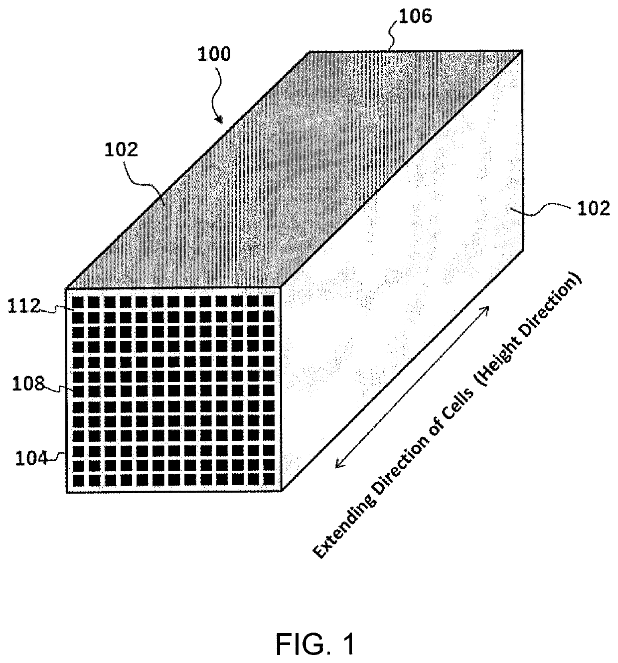
[0084]A raw material composition containing silicon carbide powder, water, a pore former and a binder was kneaded to prepare a green body. The green body was extruded to obtain a honeycomb formed body having a cuboid shape with a length of 42 mm×a width of 42 mm×a height of 415 mm, in which each cell extended in the height direction and a cell density was 465 kcells / m2 (300 cpsi). The honeycomb formed body was placed in a dryer and dried with hot air at 120° C. for 1 hour.

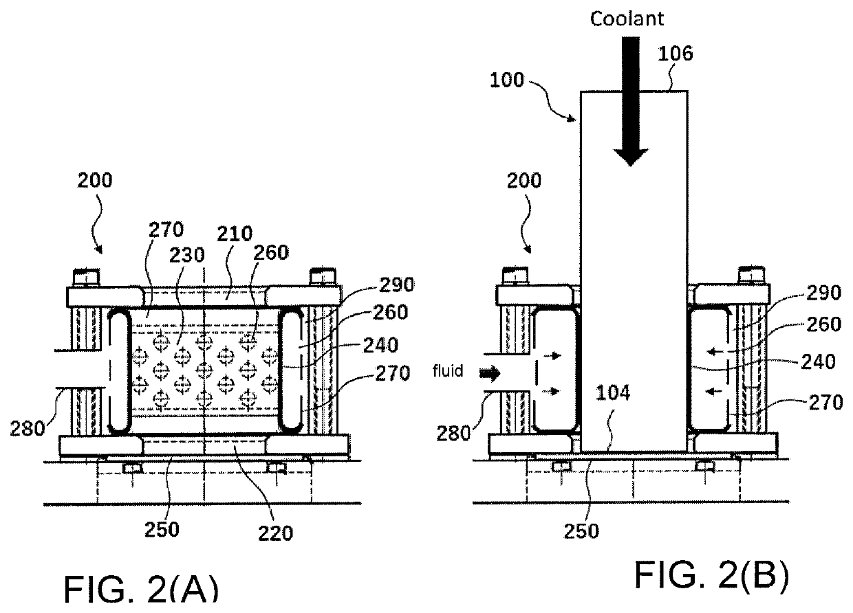
[0085]Immediately after the honeycomb formed body was removed from the dryer, the honeycomb formed body was inserted into the balloon chuck having the structure as shown in FIG. 2 such that the flow path direction of the cells was the vertical direction, until the first end face of the honeycomb formed body was brought into contact with a mesh-shaped bottom plate. The honeycomb formed body was then fixed to the balloon chuck by expanding the balloon. The communication port of the balloon chuck was communicated with...

example 2

[0092]A raw material composition containing silicon carbide powder, water, a pore former and a binder was kneaded to prepare a green body. The green body was extruded to obtain a honeycomb formed body having a cuboid shape with a length of 42 mm×a width of 42 mm×a height of 415 mm, in which each cell extended in the height direction and a cell density was 465 kcells / m2 (300 cpsi). The honeycomb formed body was placed in a dryer and dried with hot air at 120° C. for 1 hour.

[0093]Immediately after the honeycomb formed body was removed from the dryer, the honeycomb formed body was inserted into the balloon chuck having the structure as shown in FIG. 2 such that the flow path direction of the cells was the vertical direction, until the first end face of the honeycomb formed body was brought into contact with a mesh-shaped bottom plate. The honeycomb formed body was then fixed to the balloon chuck by expanding the balloon. The communication port of the balloon chuck was communicated with...


PUM

PropertyMeasurementUnit
frequencyaaaaaaaaaa
humidityaaaaaaaaaa
areaaaaaaaaaaa

Abstract

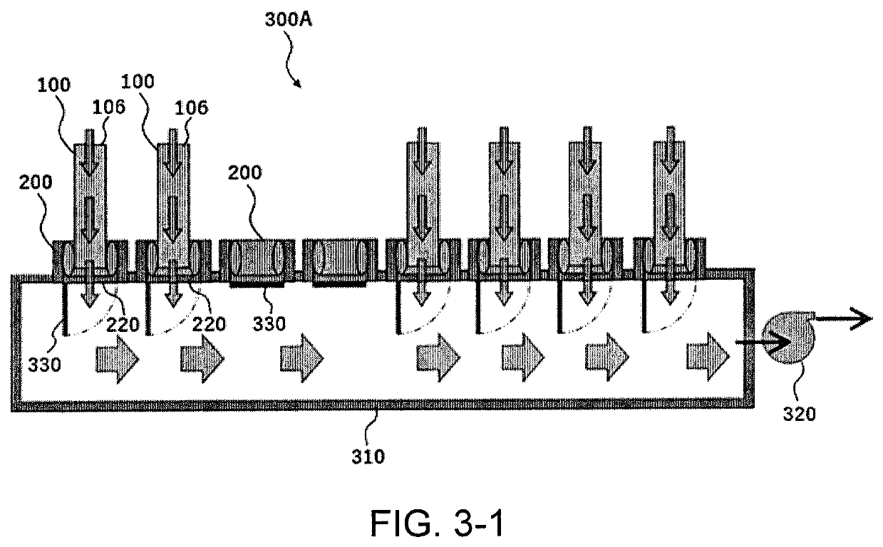
A method for producing a honeycomb structure, the method including: a step of drying a pillar-shaped honeycomb formed body including partition walls that define a plurality of cells each forming a flow path penetrating from a first end face to a second end face; and after the step of drying, a step of cooling the honeycomb formed body by applying a suction force to the first end face of the honeycomb formed body to allow a coolant to flow in the honeycomb formed body from the second end face, pass through the cells, and flow out from the first end face.

Description

FIELD OF THE INVENTION[0001]The present invention relates to a method for producing a honeycomb structure.BACKGROUND OF THE INVENTION[0002]An exhaust gas discharged from an internal combustion engine such as a diesel engine or a gasoline direct injection engine contains a large amount of particulates (particulate matters) mainly based on carbon that will cause environmental pollution. Therefore, in general, exhaust systems of the diesel engine or the like have been equipped with filters for collecting particulates, and exhaust systems of the gasoline direct injection engine are being increasingly equipped with filters for collecting particulates.[0003]As such a filter, there is known a ceramic pillar-shaped honeycomb structure including: a plurality of first cells (108a) extending from a first end face (104) to a second end face (106), the first end face (104) being opened and the second end face (106) having plugged portions (103); and a plurality of second cells (108b) extending f...

Claims


Application Information

Patent Timeline
Patent Type & Authority Patents(United States)
IPC IPC(8): C04B40/00B28B11/24B28B11/14F26B3/06C04B38/00
CPCC04B40/0075B28B11/14B28B11/24C04B38/0006F26B3/06C04B35/622C04B38/06B01D39/20C04B2235/614C04B2235/3481C04B2235/3427C04B2235/3234C04B2235/3826C04B2235/3873C04B2235/3244C04B2235/3248C04B2235/3222C04B2235/3217C04B2235/3232C04B2235/3418C04B2235/349C04B2235/3206C04B2235/442B28B11/243B28B11/006
Inventor ITADU, KENFUJIE, NOBUHIROWATANABE, YUJI
Owner NGK INSULATORS LTD
Learn More