Zero-reset device with independent hammers

a zero-reset device and independent technology, applied in the field of zero-reset devices for timepieces, can solve the problems of insufficient direct kinematic connection, potential lack of precision, and limiting the use of this device, so as to improve operation reliability, high accuracy, and simple and reliable during use.

Active Publication Date: 2015-10-20
DE LA MFG DHORLOGERIE AUDEMARS PIGUET & CIE
View PDF18 Cites 4 Cited by
  • Summary
  • Abstract
  • Description
  • Claims
  • Application Information

AI Technical Summary

Benefits of technology

[0005]One object of the present invention is therefore to overcome, at least in part, the disadvantages of the known devices and to produce a zero-reset device equipped with independent hammers, which is provided with increased operational reliability, high accuracy in terms of the simultaneous actuation of the hammers, and also a well defined force applied to the heart-shaped cams. A further object of the present invention is also to produce this device by means of a robust construction that is as compact as possible and also simple and reliable during use. The device should be adapted for implementation just as well in a chronograph mechanism per se as in any other similar application, such as a fly-back hand mechanism.
[0007]As a result of these measures, the zero reset is performed only if the manual force applied by the user of the timepiece to the first control means exceeds a predefined threshold value. In addition, the force applied by the hammers to the cams is always identical and equal to a predefined value. This is achieved whilst ensuring maximum independence of the hammers, which have no direct kinematic connection therebetween, at least not during application thereof to the cams.
[0008]These advantages can also be enhanced by arranging the winding and release means as well as the locking means advantageously, as is clear from the dependent claims. Likewise, the device comprises a return means of the zero-reset hammers able to return said hammers to the rest position thereof following actuation thereof, this return means being able to be arranged so as to maintain, in an optimal manner, the independence between the hammers. In addition, the zero-reset hammers of a device according to the present invention may advantageously all have the same geometry. All of these factors contribute to a particularly simple and reliable embodiment of such a device.

Problems solved by technology

If the proposed arrangement has springs acting independently on the hammers, it is however necessary, amongst others due to said connection element, to provide a coaxial pivoting of the hammers as well as a minute counter jumper angularly pivoted concentrically with the minute counter wheel, which considerably limits the use of this device.
However, such a direct kinematic connection is not optimal.
In addition, this implies that the mechanism does not have springs tending to apply the hammers against the hearts and the potential lack of precision has to be compensated for, also by making the arms of the hammers resilient.
It should therefore be noted that the solutions of the prior art currently known are not entirely satisfactory and / or cannot be used by all types of chronograph mechanism.

Method used


Image

  • Zero-reset device with independent hammers
  • Zero-reset device with independent hammers
  • Zero-reset device with independent hammers

Examples


first embodiment

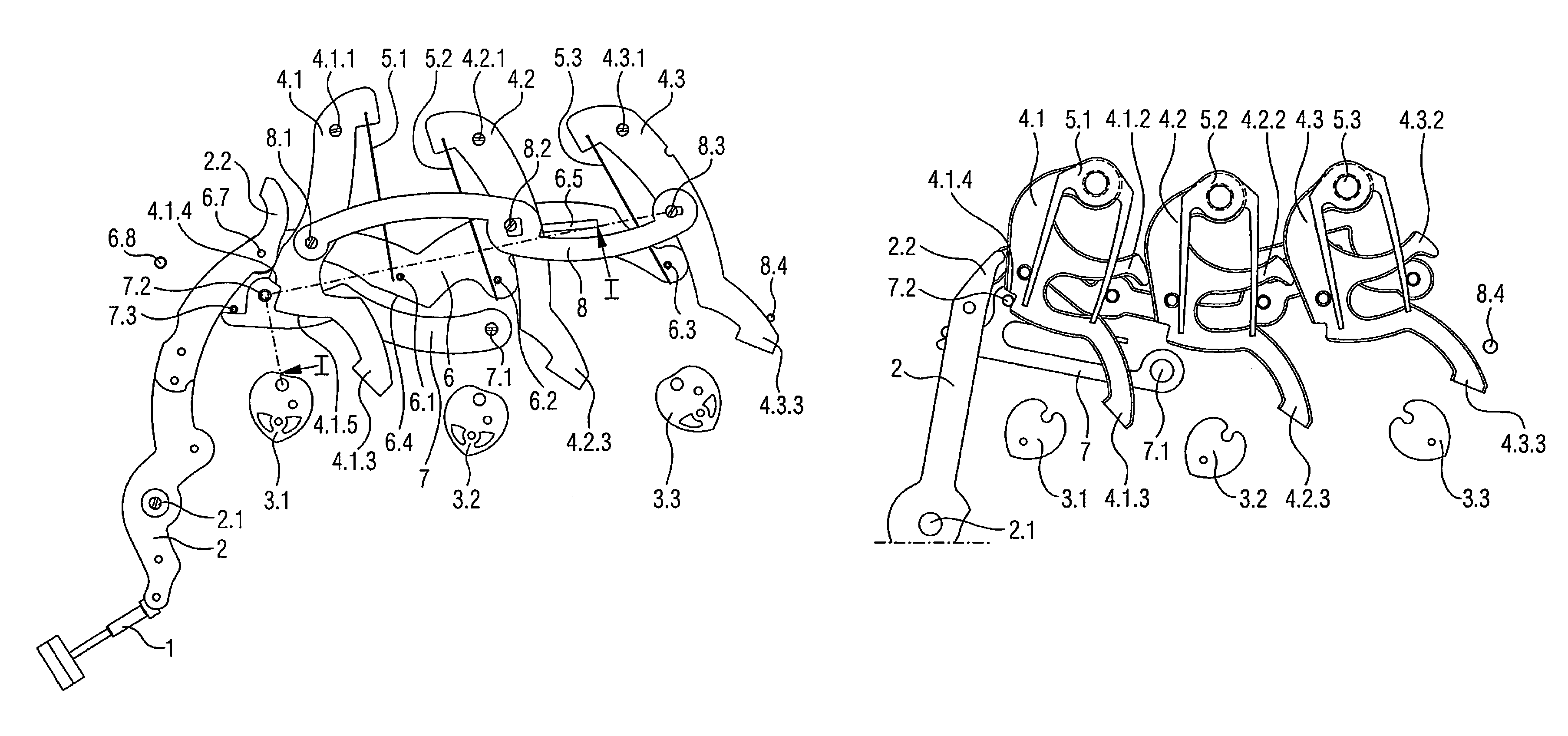
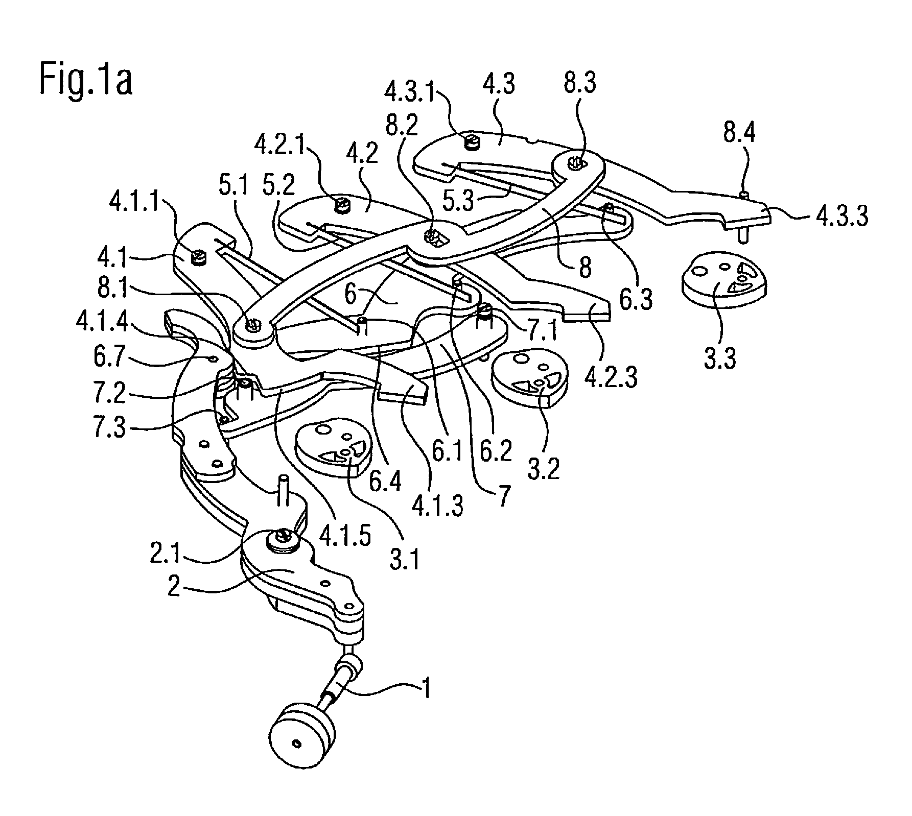
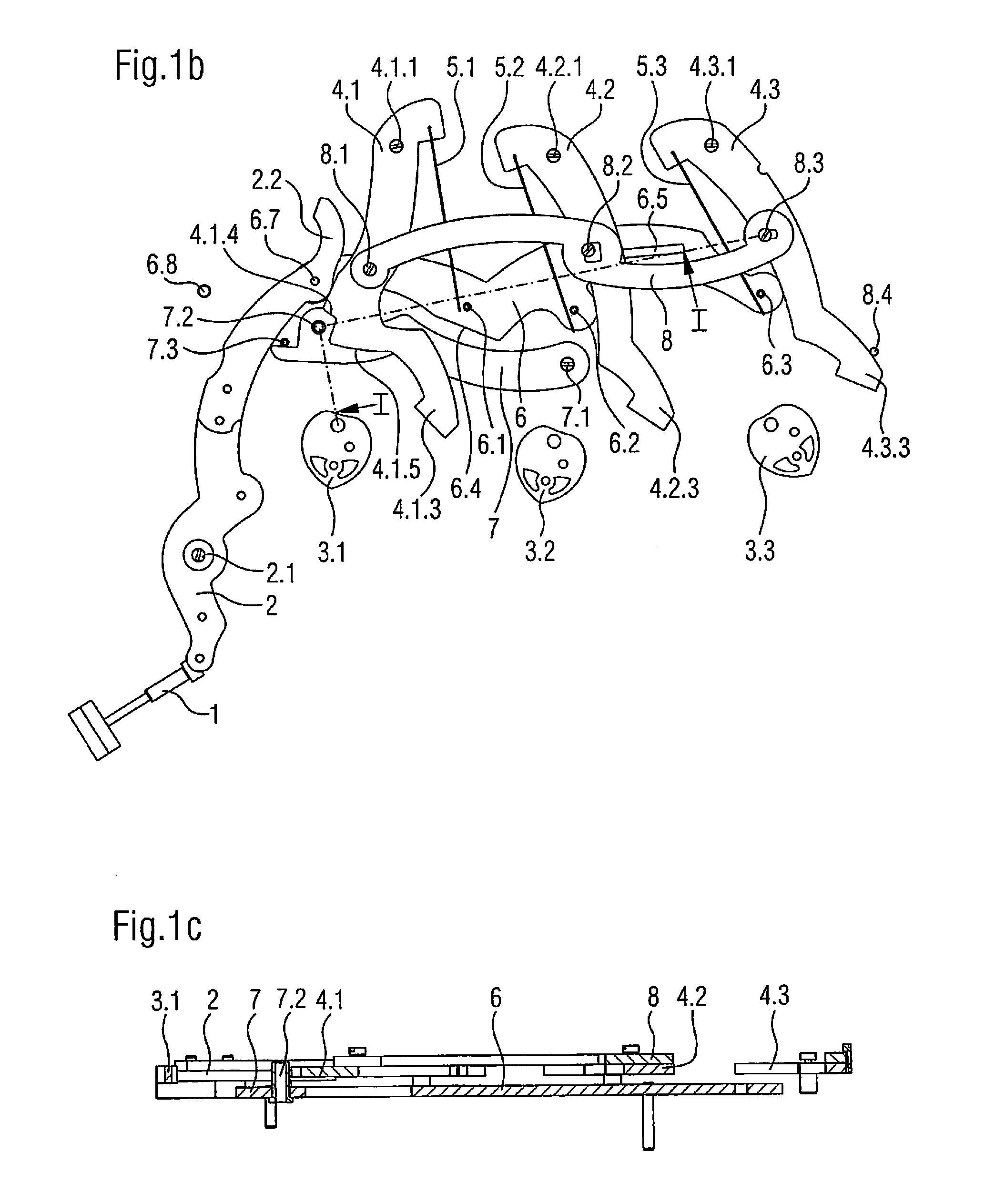
[0018]Contrary to the devices of the prior art, the device comprises at least two hammer springs 5.1, 5.2, 5.3, each of which is able to exert a press-tension force causing one of the zero-reset hammers 4.1, 4.2, 4.3 to pivot in the direction of the corresponding zero-reset cam 3.1, 3.2, 3.3, and a winding and release means or mechanism 6 as well as a locking means or mechanism 7. In the device illustrated in FIGS. 1a to 1c, the hammer springs are formed by flat springs of which one end is mounted rigidly on the corresponding hammer and of which the other end is free so as to be able to receive a winding force by means of the winding and release means 6, as will be become clearer from the following description. As can be clearly seen, the springs could be mounted on said winding and release means 6 and the free ends of said springs could cooperate with the hammers 4.1, 4.2, 4.3, this design not being illustrated in the figures.

[0019]In fact, said winding and release means 6 is able ...

second embodiment

[0032]In addition, FIGS. 3a to 3c also emphasize that the device according to this second embodiment may advantageously be equipped with zero-reset hammers 4.1, 4.2, 4.3 which all have the same geometry, such that they have an identical weight and moment of inertia. This allows to further improve the accuracy of the moment at which the hammers strike against the respective heart thereof, given that, aside from manufacturing tolerances, said hammers in this figure should all demonstrate the same behavior.

[0033]It is also noted in FIGS. 3a to 3c that the hammer springs 5.1, 5.2, 5.3 of the second embodiment of the device are preferably formed by flat springs having two resilient arms, of which the first arm serves to receive a winding force by means of the winding and release means 6, similarly to the free end of the flat springs of the first embodiment of the device, and of which the second arm serves to transmit the winding force, once the springs have been wound, to the correspondi...


PUM


Abstract

A zero-rest device for a timepiece, including first and second control mechanisms, two zero-reset cams, and two corresponding zero-reset hammers configured to cooperate with the cams. The device also includes two hammer springs exerting a pre-stress force causing a hammer to pivot in the direction of its corresponding cam, a winding and release mechanism and a locking mechanism. The winding and release mechanism is configured to wind the hammer springs during a first phase of an actuation of the first control mechanism and to cooperate, during a second phase of this actuation, with the locking means, such that the locking means passes from a rest position in which the locking means holds the hammers to a release position in which the locking means releases the hammers, which come, in each case under the action of the corresponding hammer spring, into the positions thereof of cooperation with the corresponding cam.

Description

RELATED APPLICATION[0001]The present application claims priority to Swiss Patent Application No. CH 02080 / 13 filed Dec. 16, 2013, the disclosure of which is hereby incorporated by reference herein in its entirety.FIELD OF THE INVENTION[0002]The present invention relates to a zero-reset device for a timepiece, in particular for a chronograph watch, the device comprising a first control means, a second control means connected kinematically to said first control means, at least two zero-reset cams, as well as at least two corresponding zero-reset hammers, which are pivoted independently of one another and can be actuated so as to cooperate with a corresponding zero-reset cam.[0003]This invention more specifically relates to timepieces, in particular wristwatches, having a mechanical movement and being equipped with a chronograph mechanism or a fly-back hand. In this context, it is common for the second, minute and hour hands, possibly arranged as fly-back hands, to each be mounted on a...

Claims


Application Information

Patent Timeline
Patent Type & Authority Patents(United States)
IPC IPC(8): G04F7/06G04F7/08
CPCG04F7/0809G04F7/062G04F7/0814G04F7/0819
Inventor PHILIPPINE, THIBAUTGABATHULER, JACQUESMONTET, JOHAN
Owner DE LA MFG DHORLOGERIE AUDEMARS PIGUET & CIE
Why Eureka
Try Eureka