Magnetic resonance imaging apparatus and magnetic resonance imaging method

a magnetic resonance imaging and magnetic resonance imaging technology, applied in the field of magnetic resonance imaging apparatus and magnetic resonance imaging method, can solve the problems of long time in the imager for the subject, long time required, and long imaging tim

Active Publication Date: 2015-10-27
TOSHIBA MEDICAL SYST CORP
View PDF11 Cites 4 Cited by
  • Summary
  • Abstract
  • Description
  • Claims
  • Application Information

AI Technical Summary

Benefits of technology

[0003]The present invention relates to a magnetic resonance imaging apparatus and a magnetic resonance imaging method.

Problems solved by technology

However, according to the technique of the ECG gated imaging, when irregularity in the heart beat is sometimes induced by a motion or an irregular pulse of a subject in some cases, a doctor has to read an abnormal image (ghost image) or an image with a phase shift.
However, such conventional technology described above has a problem that an imaging time becomes long.
As a result, collected data is discarded, a long imaging time is wasted, and moreover, retry of imaging from the beginning results in a long time required for imaging, which causes a long time in the imager for the subject.

Method used


Image

  • Magnetic resonance imaging apparatus and magnetic resonance imaging method
  • Magnetic resonance imaging apparatus and magnetic resonance imaging method
  • Magnetic resonance imaging apparatus and magnetic resonance imaging method

Examples


first embodiment

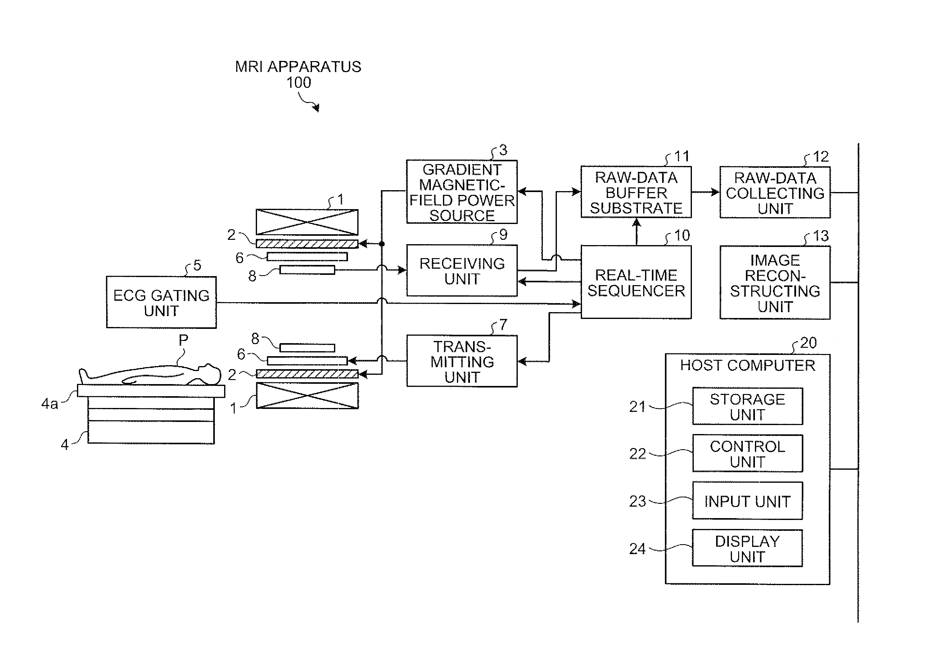
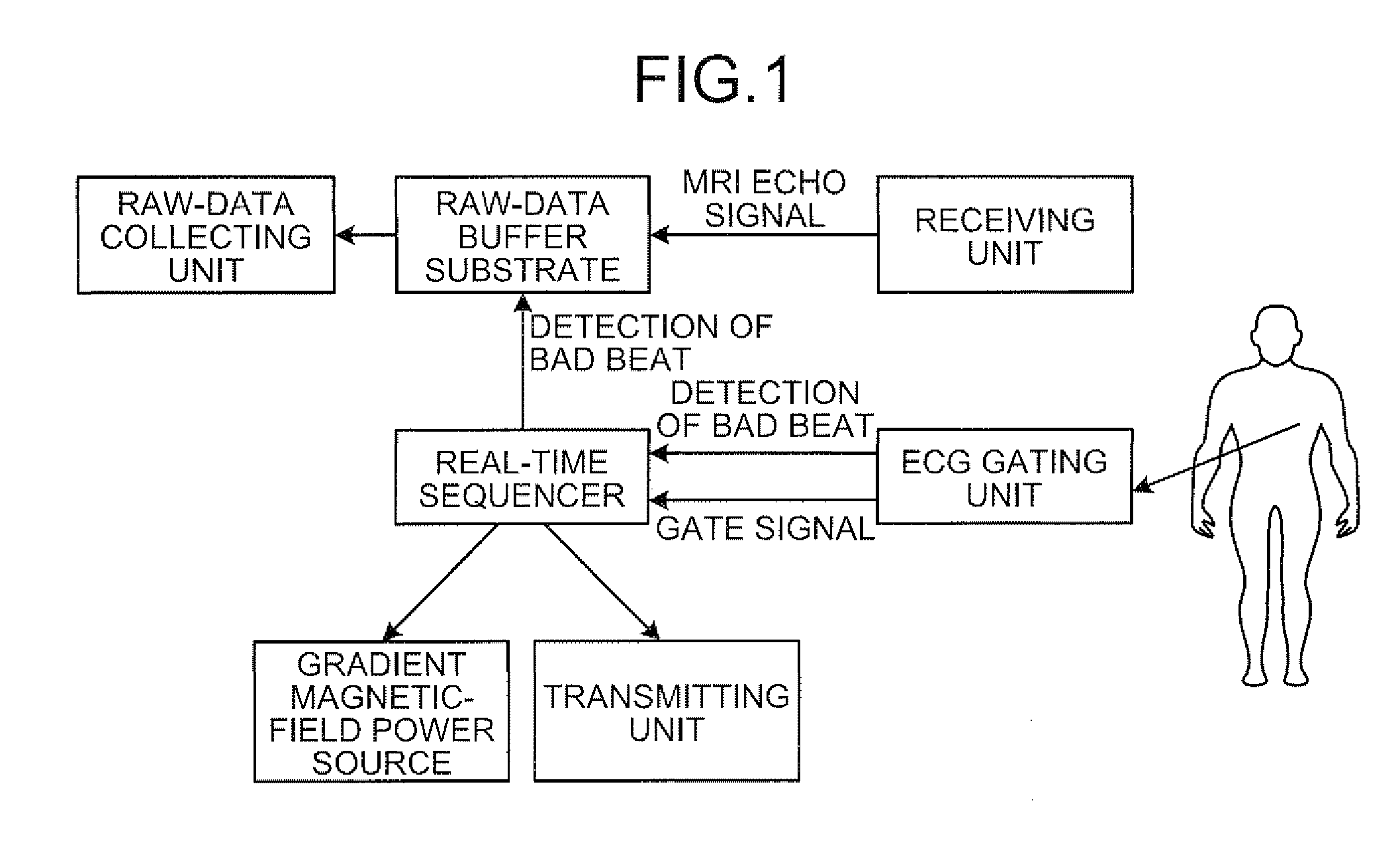
[0010]FIG. 1 is a schematic diagram for explaining an outline of a Magnetic Resonance Imaging (MRI) apparatus according to the present invention;

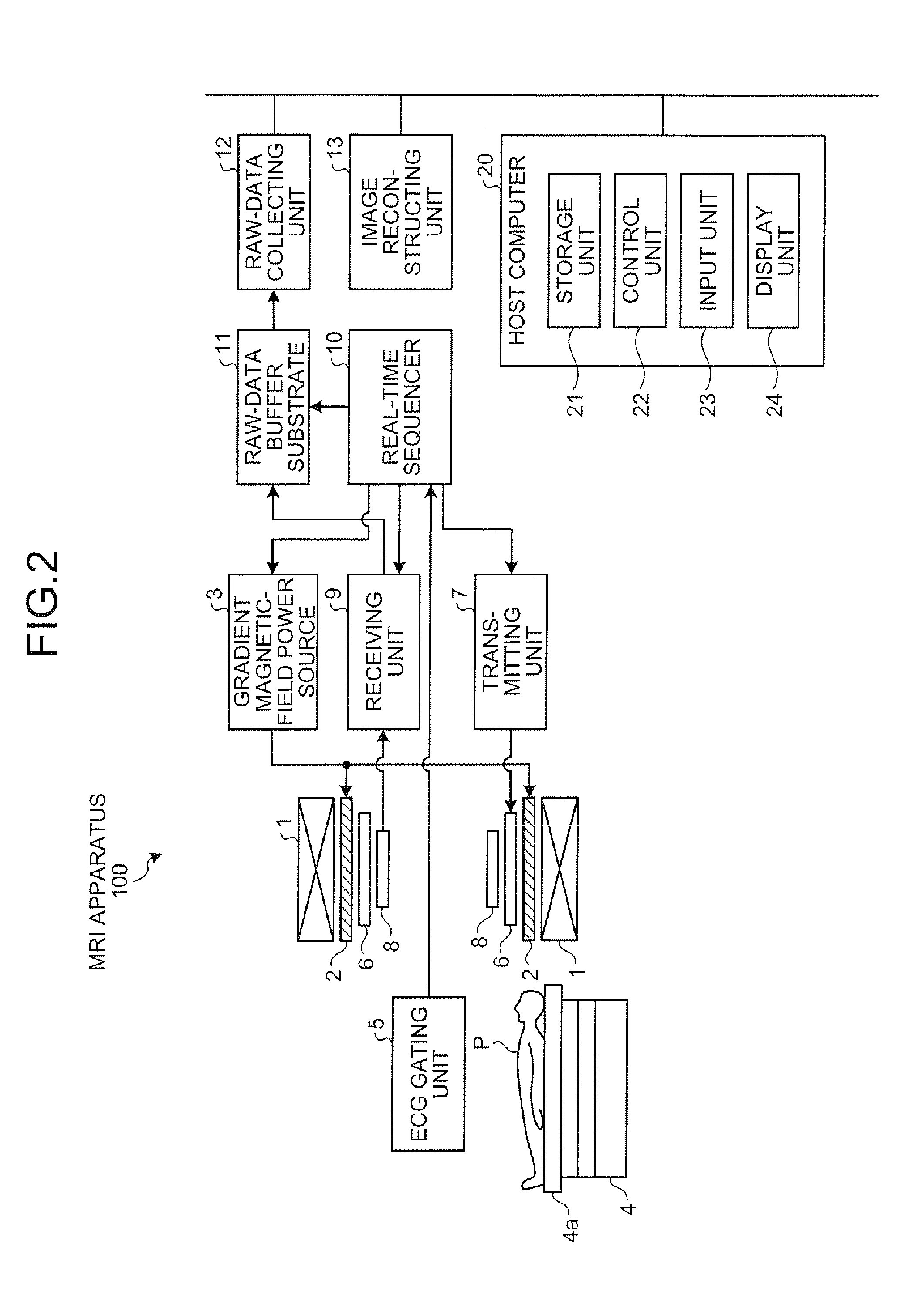
[0011]FIG. 2 is a functional block diagram of a configuration of the MRI apparatus according to the first embodiment;

[0012]FIGS. 3 and 4 are Electrocardiogram (ECG) gating timing charts;

[0013]FIG. 5 is a schematic diagram for explaining an imaging method;

[0014]FIG. 6 is a schematic diagram for explaining sequence information;

[0015]FIG. 7 is a schematic diagram for explaining transfer control on transferring raw data;

[0016]FIGS. 8A and 8B are flowcharts of process procedures performed by a real-time sequencer;

[0017]FIG. 9 is a flowchart of a process procedure performed by a raw-data buffer substrate;

[0018]FIG. 10 is a schematic diagram for explaining transfer control on transferring raw data;

[0019]FIG. 11 is a flowchart of a process procedure performed by a real-time sequencer;

[0020]FIG. 12 is an ECG-gating timing chart;

[0021]FIG. 13 is an E...


PUM


Abstract

A magnetic resonance imaging apparatus collects raw data about a subject in a synchronized manner with an electrocardiographic signal of the subject. An Electrocardiogram (ECG) gating unit detects an irregular synchronization interval with respect to the electrocardiographic signal. When the ECG gating unit detects an irregular synchronization interval, a real-time sequencer controls a gradient magnetic-field power source, a transmitting unit, and the like so as to reacquire raw data that is acquired during the irregular synchronization interval.

Description

CROSS-REFERENCE TO RELATED APPLICATIONS[0001]This application is based upon and claims the benefit of priority from the prior Japanese Patent Application No. 2009-25286, filed on Feb. 5, 2009, and No. 2009-283205, filed on Dec. 14, 2009; the entire contents of which are incorporated herein by reference.BACKGROUND OF THE INVENTION[0002]1. Technical Field[0003]The present invention relates to a magnetic resonance imaging apparatus and a magnetic resonance imaging method.[0004]2. Related Art[0005]Recently, when taking a medical image of a circulatory system, a technique of Electrocardiogram (ECG) gated imaging by which imaging is performed in a synchronized manner with electrocardiographic signals of a subject is used. For example, a technique of ECG gated imaging performed by a magnetic resonance imaging apparatus is disclosed in JP-A 2008-125986 (KOKAI).[0006]However, according to the technique of the ECG gated imaging, when irregularity in the heart beat is sometimes induced by a mo...

Claims


Application Information

Patent Timeline
Patent Type & Authority Patents(United States)
IPC IPC(8): A61B5/055G01R33/567
CPCA61B5/055G01R33/5673
Inventor MORI, AKIO
Owner TOSHIBA MEDICAL SYST CORP
Why Eureka
Try Eureka