Methods and apparatus for image fusion

a technology of image fusion and apparatus, applied in the field of methods and apparatus for image fusion, can solve the problems of high transmission loss, increased size, cost and power requirements of such systems, and possible coherence effects

Active Publication Date: 2015-10-27
RAYTHEON CO
View PDF26 Cites 17 Cited by
  • Summary
  • Abstract
  • Description
  • Claims
  • Application Information

AI Technical Summary

Problems solved by technology

The need for additional hardware (beyond a single image sensor and associated optics) as well as computational resources (to provide the digital image combination) increases the size, cost and power requirements of such systems.
However, this approach leads to high transmission loss, possible coherence effects, and becomes difficult, if not impossible, as the image bandwidth increases.

Method used


Image

  • Methods and apparatus for image fusion
  • Methods and apparatus for image fusion
  • Methods and apparatus for image fusion

Examples


Embodiment Construction

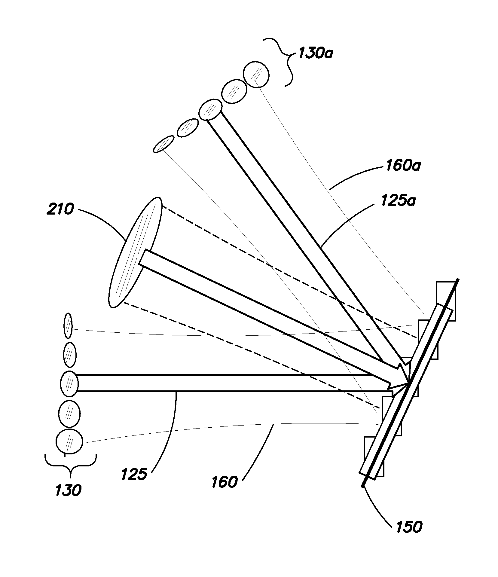
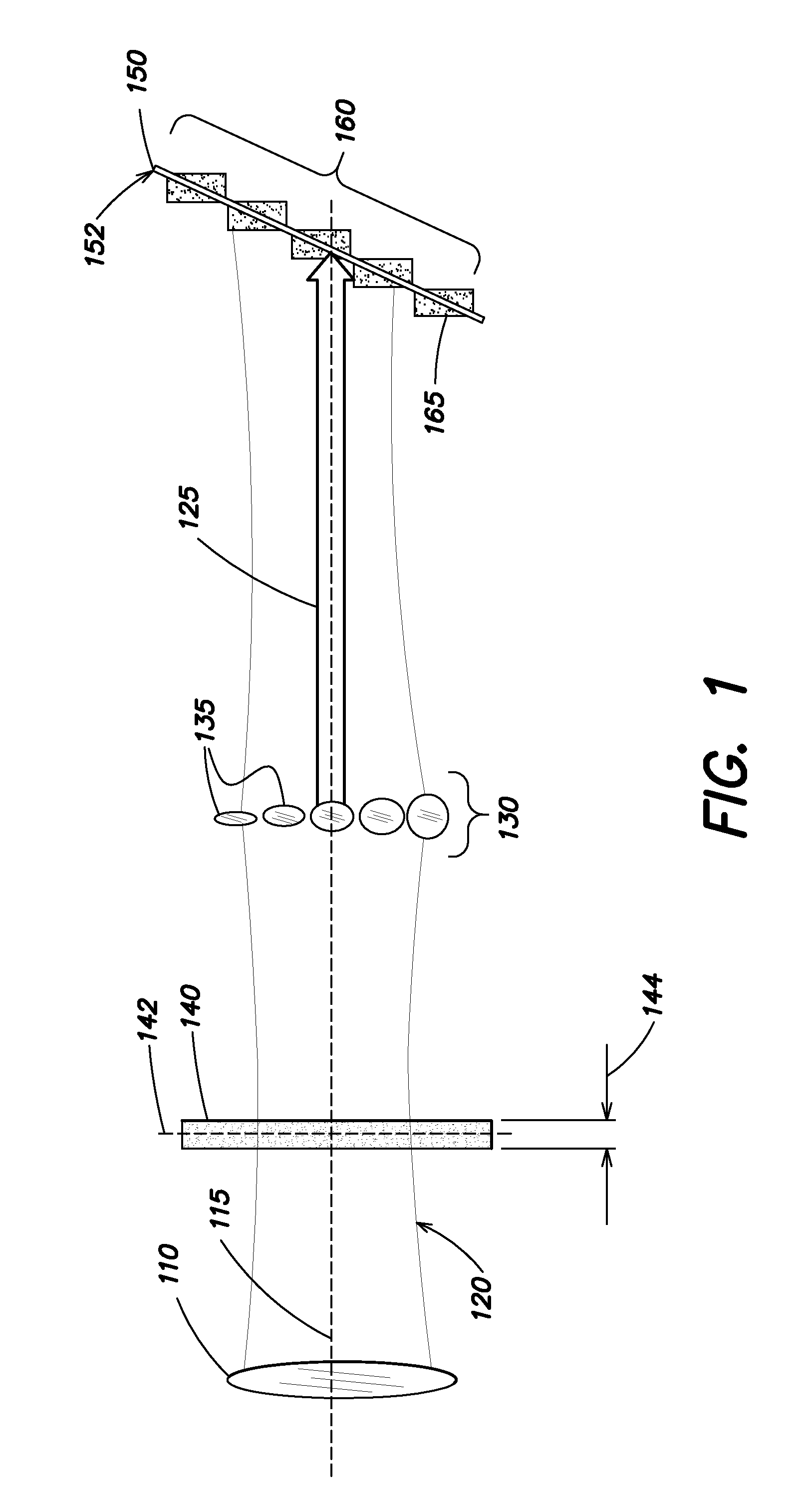
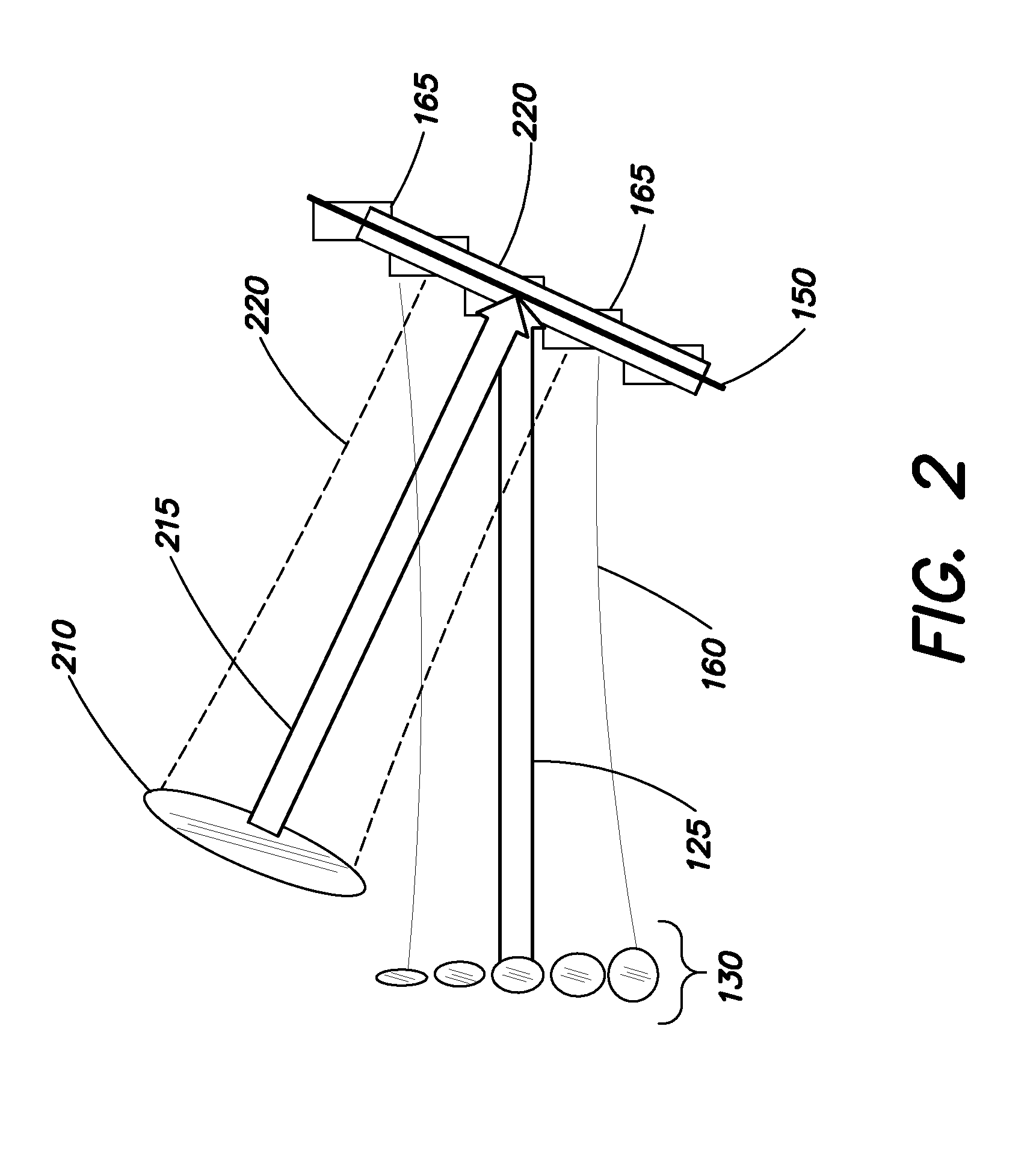
[0017]Aspects and embodiments are directed to an imaging system that is capable of fusing multiple images on one imaging sensor plane without requiring the use of beamsplitters. Conventional imaging requires that the optical axis of the imaging system align to the surface normal of the imaging detector in order to keep the image in focus. Aspects and embodiments are directed to the use of “sliced source” imaging techniques in which this requirement of normal incidence is relaxed and images may be formed, in-focus, at non-normal angles of incidence on the detector plane. Using sliced-source imaging techniques, the object or an image of the object is divided into a series of slices that are individually reimaged onto a tilted image plane. The imaging detector, aligned with this tilted image plane, reconstructs an in-focus image from the series of slices, as discussed further below. Thus, since the imaging detector is able to obtain in-focus images from electromagnetic radiation incide...


PUM


Abstract

Systems and methods configured to implement sliced source imaging to produce a plurality of overlapping in-focus images on the same location of a single imaging detector without using beamsplitters.

Description

FEDERALLY SPONSORED RESEARCH[0001]This invention was made with government support (Grant No. and federal agency withheld). The government of the United States has certain rights in this invention.BACKGROUND[0002]Image fusion, or the combination of multiple images of the same or similar scene(s), is used to achieve a higher resolution image of the scene, or an image containing more information about the scene than may be typically obtained from a single image of the scene. A traditional approach to image fusion uses software to digitally combine image data acquired from separate image sensors. This approach requires multiple image sensors, and optionally multiple optical sub-systems to direct electromagnetic radiation to each of the image sensors. The need for additional hardware (beyond a single image sensor and associated optics) as well as computational resources (to provide the digital image combination) increases the size, cost and power requirements of such systems. Another con...

Claims


Application Information

Patent Timeline
Patent Type & Authority Patents(United States)
IPC IPC(8): G06K9/00H04N5/33H04N5/232H04N5/225G06K9/20G02B27/10G06V10/147
CPCG06K9/209H04N5/2254H04N5/23238H04N5/332G02B27/1066G06K2009/2045G06V10/147H04N23/60H04N23/698H04N23/11
Inventor KOWALEVICZ, ANDREW
Owner RAYTHEON CO
Why Eureka
Try Eureka