
Active imaging device and method for speckle noise reduction

a technology of active imaging and noise reduction, which is applied in the field of active imaging devices, can solve the problems of inability to use active imaging techniques, random fluctuations in return signals, and degrade the quality of images obtained by active imaging devices, and achieve the effect of small effort and effective reduction of speckle nois

Active Publication Date: 2011-11-10
SONY CORP
View PDF10 Cites 5 Cited by
  • Summary
  • Abstract
  • Description
  • Claims
  • Application Information

AI Technical Summary

Benefits of technology

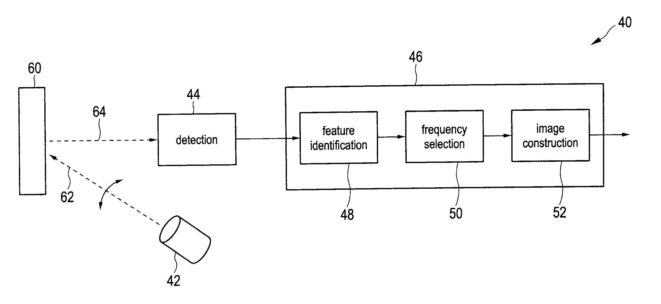
[0007]It is an object of the present invention to provide an active imaging device and method, by which speckle noise occurring during active imaging can be effectively reduced with small efforts. It is a further object of the present invention to provide a corresponding image processing device and method as well as a corresponding computer program for implementing said image processing method and a computer readable medium.
[0024]For a transmitter with a given set of illuminated frequencies, the best selected combination of these illuminated frequencies at the receiver (to reduce speckle) is thus found and combined for each image feature. The selection of combinations for each feature can be done in parallel at the receiver and therefore the object can be scanned very quickly.

Problems solved by technology

Speckle noise (also called “speckle” in the following) is a granular noise that inherently exists in and degrades the quality of images obtained by active imaging devices, such as active radars, and synthetic aperture radars (SARs).
Speckle noise in conventional radar results from random fluctuations in the return signal from an object that is no bigger than a single image-processing element.
Such techniques however cannot be used for an active imaging device, since it is important that the transmitted signal in an active imaging device maintains its phase coherence.

Method used


Image

  • Active imaging device and method for speckle noise reduction
  • Active imaging device and method for speckle noise reduction
  • Active imaging device and method for speckle noise reduction

Examples


first embodiment

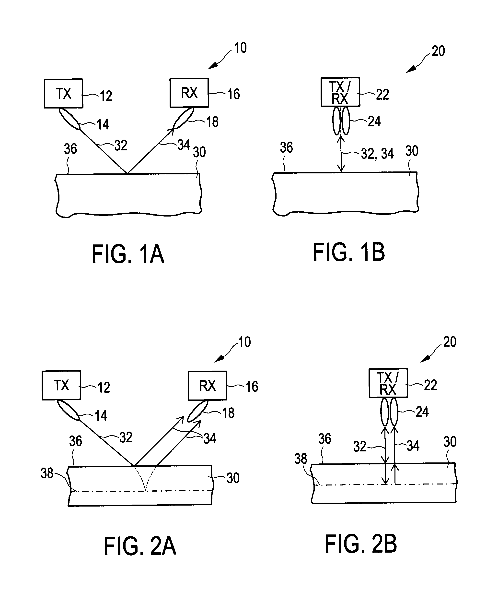
[0035]FIG. 1 shows an active imaging device,

[0036]FIG. 2 shows a first embodiment of an active imaging device,

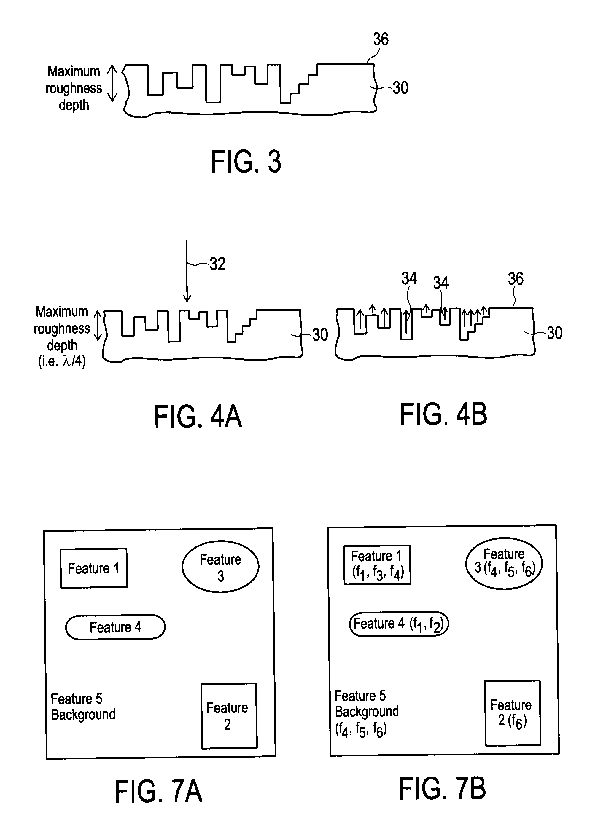
[0037]FIG. 3 shows a diagram illustrating a rough surface of an object,

[0038]FIG. 4 shows a diagram illustrating the generation of speckle noise on a rough surface,

[0039]FIG. 5 shows a first embodiment of an active imaging device according to the present invention,

[0040]FIG. 6 shows a flow chart of a first embodiment of an active imaging method according to the present invention,

[0041]FIG. 7 shows a diagram illustrating feature selection according to the present invention,

second embodiment

[0042]FIG. 8 shows an active imaging device according to the present invention, and

[0043]FIG. 9 shows a flow chart of a second embodiment of an active imaging method according to the present invention.

DETAILED DESCRIPTION OF THE INVENTION

[0044]Active imaging systems are becoming increasingly more popular at ultrasonic, microwave, millimetre and terahertz frequencies for a number of applications including medical and security applications.

[0045]The arrangement of transmitter and receiver in an active imaging system may take on many different forms, but in the most general sense active systems use a transmitter (generally an “illumination means”) to illuminate the object (or item, in general the “scene”) to be studied by transmitting at the frequency (or frequencies) of interest and analyse the received signal due to reflections and / or transmission characteristics of the object. The present invention is primarily directed to active imaging using the reflected signal, although the idea...

embodiment 40

[0068]To simplify the explanation it has been assumed that the transmitter (or illuminator) is subsequently illuminating the object using multiple discrete frequencies. The proposed imaging method can, however, also be used when the transmitter is using a wideband illumination signal coving a frequency band Δf (i.e. not consisting of discrete frequencies), such as would be produced from a pulse based active imaging system, or when the transmitter is using a illumination signal simultaneously comprising a number of discrete frequencies or small frequency bands). A corresponding embodiment 40′ of an active imaging device is depicted in FIG. 8, a corresponding embodiment of an active imaging method is depicted in FIG. 9. In this case the illuminator 42′ illumination the scene 60 with the wideband illumination signal (step 510′), and the detector 44′ receives a single detection data set (step S12′).

[0069]In this case the processor 46′ would need to examine different frequency components...


PUM


Abstract

The present invention relates to an active imaging device for imaging a scene, comprising a scene illuminator that illuminates said scene with radiation at multiple illumination frequencies or an illumination frequency range covering multiple illumination frequencies, a radiation detector that detects radiation received from said scene in response to said illumination and that generates detection data from said detected radiation, a feature identifier that analyses said detection data and identifies different features in said scene, a frequency selector that separately selects for the identified features one or more selected illumination frequencies resulting in the minimum speckle noise in an image of the respective feature constructed from the detection data, which have been generated from radiation received in response to the illumination of the scene with radiation at said one or more selected illumination frequencies, and an image constructor that constructs a final image from the detection data, wherein the image portions of the identified features are constructed from the detection data, which have been generated from radiation received in response to the illumination of the scene with radiation at said one or more selected illumination frequencies, and wherein said image portions are combined into the final image.

Description

CROSS-REFERENCE TO RELATED APPLICATIONS[0001]The present application claims priority of European patent application 10 161 881.7 filed on May 4, 2010.FIELD OF THE INVENTION[0002]The present invention relates to an active imaging device and a corresponding method for imaging a scene. The present invention relates further to an image processing device and method for use in an active imaging device and method. Still further, the present invention relates to a computer readable non-transitory medium storing a computer program. The present invention particularly directed to the reduction of speckle noise.BACKGROUND OF THE INVENTION[0003]Speckle noise (also called “speckle” in the following) is a granular noise that inherently exists in and degrades the quality of images obtained by active imaging devices, such as active radars, and synthetic aperture radars (SARs). Speckle noise in conventional radar results from random fluctuations in the return signal from an object that is no bigger t...

Claims


Application Information

Patent Timeline
Patent Type & Authority Applications(United States)
IPC IPC(8): H04N9/73G01S17/89
CPCG01S7/411G01S7/4802G01S7/52046G01S7/52077G01S13/89G06T2207/20221G01S17/89G06T5/002G06T5/50G06T2207/10152G01S15/8906G06T5/70
Inventor STIRLING-GALLACHER, RICHARD
Owner SONY CORP
Learn More