
Optical imaging transmitter with brightness enhancement

A transmitter, optical transmitter technology, applied in optical radiation measurement, optics, optical components, etc., can solve the problem of LIDAR system unable to detect dark objects and so on

Pending Publication Date: 2020-03-24
OUSTER INC
View PDF5 Cites 4 Cited by
  • Summary
  • Abstract
  • Description
  • Claims
  • Application Information

AI Technical Summary

Problems solved by technology

This can cause LIDAR systems to fail to detect dark objects that occupy the field of view near the field of view occupied by the retroreflector

Method used


Image

  • Optical imaging transmitter with brightness enhancement
  • Optical imaging transmitter with brightness enhancement
  • Optical imaging transmitter with brightness enhancement

Examples


Embodiment Construction

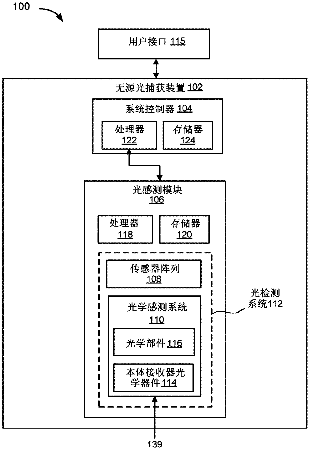
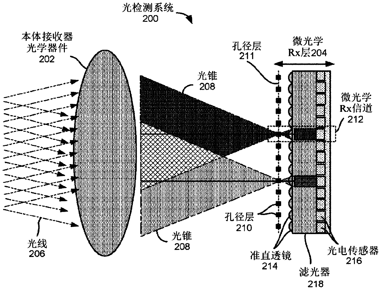
[0049] Some embodiments of the present disclosure relate to optical imager systems that can generate images from ambient light within a field and / or light reflected from objects within the field emitted by optical transmitters. For example, in some embodiments, the optical imager system may be a passive system that does not actively illuminate a scene or a given area, but instead detects ambient light in the scene or area that is generated by Reflected by one or more objects. The passive optical imager system may include a light sensing module for receiving ambient light within the field. The light sensing module may be a Wide Field of View Narrow Band Optical Imaging System (WFNBI) that collects imaging information. The light sensing module may include one or more body receiver optics, a micro-optical receiver system, and a system controller for operating the light sensing module. According to some embodiments of the present disclosure, a micro-optical receiver system may i...


PUM


Abstract

Embodiments describe optical imagers that include one or more micro-optic components. Some imagers can be passive imagers that include a light detection system for receiving ambient light from a field. Some imagers can be active imagers that include a light emission system in addition to the light detection system. The light emission system can be configured to emit light into the field such thatemitted light is reflected off surfaces of an object in the field and received by the light detection system. In some embodiments, the light detection system and / or the light emission system includesmicro-optic components for improving operational performance.

Description

[0001] Cross References to Related Applications [0002] This application claims U.S. Provisional Patent Application No. 62 / 506,449, filed May 15, 2017, U.S. Provisional Patent Application No. 62 / 506,437, filed May 15, 2017, U.S. Provisional Patent Application No. 62 / 506,437, filed May 15, 2017 Application Serial No. 62 / 506,445 and priority to U.S. Provisional Patent Application Serial No. 62 / 515,291, filed June 5, 2017, the entire contents of which are hereby incorporated by reference for all purposes. Background technique [0003] Imagers detect light and create a digital image of a scene based on the detected light. An image consists of a fixed number of rows and columns of pixels, where each pixel maps to a different field of view in the scene. Electronic imagers typically utilize photodetectors to convert light into electrical signals. Each photodetector is located at a different location on the focal plane, typically corresponding to a single pixel or component of a pi...

Claims


Application Information

Patent Timeline
IPC IPC(8): G01J1/02G01J1/08G01J1/44G01S17/10G01S7/486G01S7/4863G01S7/4865G01S17/89G01S17/931
CPCG01S7/4814G01S17/10G01S17/42G01S7/4816G01S7/4863G01S7/4865H01L31/02162H01L31/02164H01L31/02325G01S17/89H01L27/14643H01L31/02027G01S7/4813G01S7/4815G01S7/4817G01S17/08H01L27/1446H01L31/02165H01L31/107G02B27/46G01S17/931G02B27/0955G02B27/0037G02B27/30H01L31/02327H04B10/503H04B10/6973H04B10/801G02B5/205G01S7/486H04B10/675
Inventor A·帕卡拉M·弗里赫特E·扬M·舒
Owner OUSTER INC
Learn More