
Defect detection device and method

A defect detection and polarization direction technology, applied in the field of optical detection, can solve problems such as false detection, increased workload, detection of areas near reflections, etc., achieve fast response speed, improve defect detection and recognition accuracy, improve defect detection and The effect of recognition speed

Active Publication Date: 2021-04-23
上海御微半导体技术有限公司
View PDF4 Cites 5 Cited by
  • Summary
  • Abstract
  • Description
  • Claims
  • Application Information

AI Technical Summary

Problems solved by technology

Traditional AOI inspection devices cannot detect real defects in the area near the reflection in this case
In addition, the traditional AOI inspection device may also identify the reflection in the mirror area as a defect, resulting in a large number of false detections and increasing the workload of subsequent re-inspection, removal or defect repair operations

Method used


Image

  • Defect detection device and method
  • Defect detection device and method
  • Defect detection device and method

Examples


Embodiment Construction

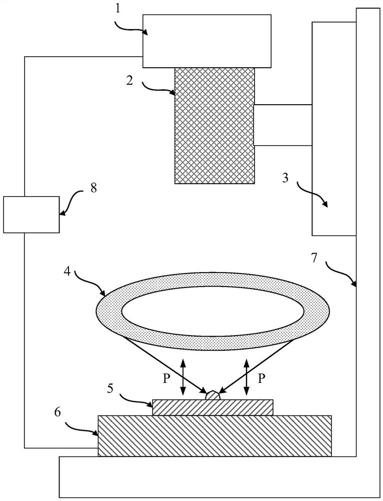
[0060]The present invention is further detailed in conjunction with the accompanying drawings and examples. It will be appreciated that the specific embodiments described herein are merely illustrative of the invention and are not limited thereto. It will also be noted that in order to facilitate the description, only the parts associated with the present invention are shown in the drawings rather than all structures.

[0061]figure 1 Schematic diagram of metal film stamping angle and particle defects under dark field lighting conditions, referencefigure 1 The detection process of ordinary particle defect 1 'on the metal film is shown, wherein the metal film may, for example, a mask plate, a mask plate including a metal film stamping process, resulting in an inclined surface formed by the upper and lower surface of the metal film. The oblique shot dark field illumination beam (non-polarized light) illuminates the ordinary particle defect 1 ', and the partial light is absorbed by the or...


PUM


Abstract

The invention provides a defect detection device and method, the defect detection device comprises a dark field illumination light source, an imaging lens, a full Stokes polarization integral camera, a motion table and a control unit, the dark field illumination light source is used for providing a linearly polarized light beam, and the motion table is used for bearing a to-be-detected sample; the linearly polarized light beam is obliquely projected to a to-be-detected sample and forms a signal light beam after being reflected and scattered by the to-be-detected sample, and the signal light beam is projected to the full Stokes polarization integral camera after passing through the imaging lens; the control unit drives the motion platform to move, so that the full-Stokes polarization integral camera completes scanning and shooting of the to-be-detected sample to form a full-Stokes polarization picture at the same time, defect detection is carried out after mirror reflection signals in the data are filtered out through data processing of the full-Stokes polarization picture, and the defect information of the to-be-detected sample is obtained. According to the invention, the defect detection and identification speed and accuracy are improved.

Description

Technical field[0001]The present invention relates to optical detection techniques, and more particularly to a defect detecting apparatus and method.Background technique[0002]AOI (Automated Optical Inspection Automatic Optical Inspection) The device is used as an optical defect detection tool, which is widely used in solar cells, integrated circuits, display panels and other industries to achieve rapid loss of removing of mask plates and wafer defects.[0003]Traditional AOI defect detecting devices typically use the tomographic, dark field, and backlight illumination. Increase the defective signal to be tested, inhibit the background signal and environmental noise, and improve the defect signal signal noise ratio. High-speed detection is then tested by high-resolution lenses and cameras. Finally, through software algorithms, the correct identification and classification of defects is achieved, and the detected defect feedback will be retrieved, clear, or defective. The correctness of...

Claims


Application Information

Patent Timeline
IPC IPC(8): G01N21/88
CPCG01N21/88G01N21/8806G01N21/8851G01N2021/8848G01N2021/8822G01N2021/8887G01N2021/8854Y02E10/50
Inventor 杨朝兴
Owner 上海御微半导体技术有限公司
Learn More