Eureka AIR delivers breakthrough ideas for toughest innovation challenges, trusted by R&D personnel around the world.

Buckling mechanism for a tape drive loader

a tape drive and loader technology, applied in the field of tape drives, can solve the problems of reducing the overall footprint of the buckler mechanism, reducing the footprint of the loader mechanism, and lowering the torque of the drive motor

Active Publication Date: 2015-10-27
ORACLE INT CORP
View PDF2 Cites 4 Cited by
  • Summary
  • Abstract
  • Description
  • Claims
  • Application Information

AI Technical Summary

Benefits of technology

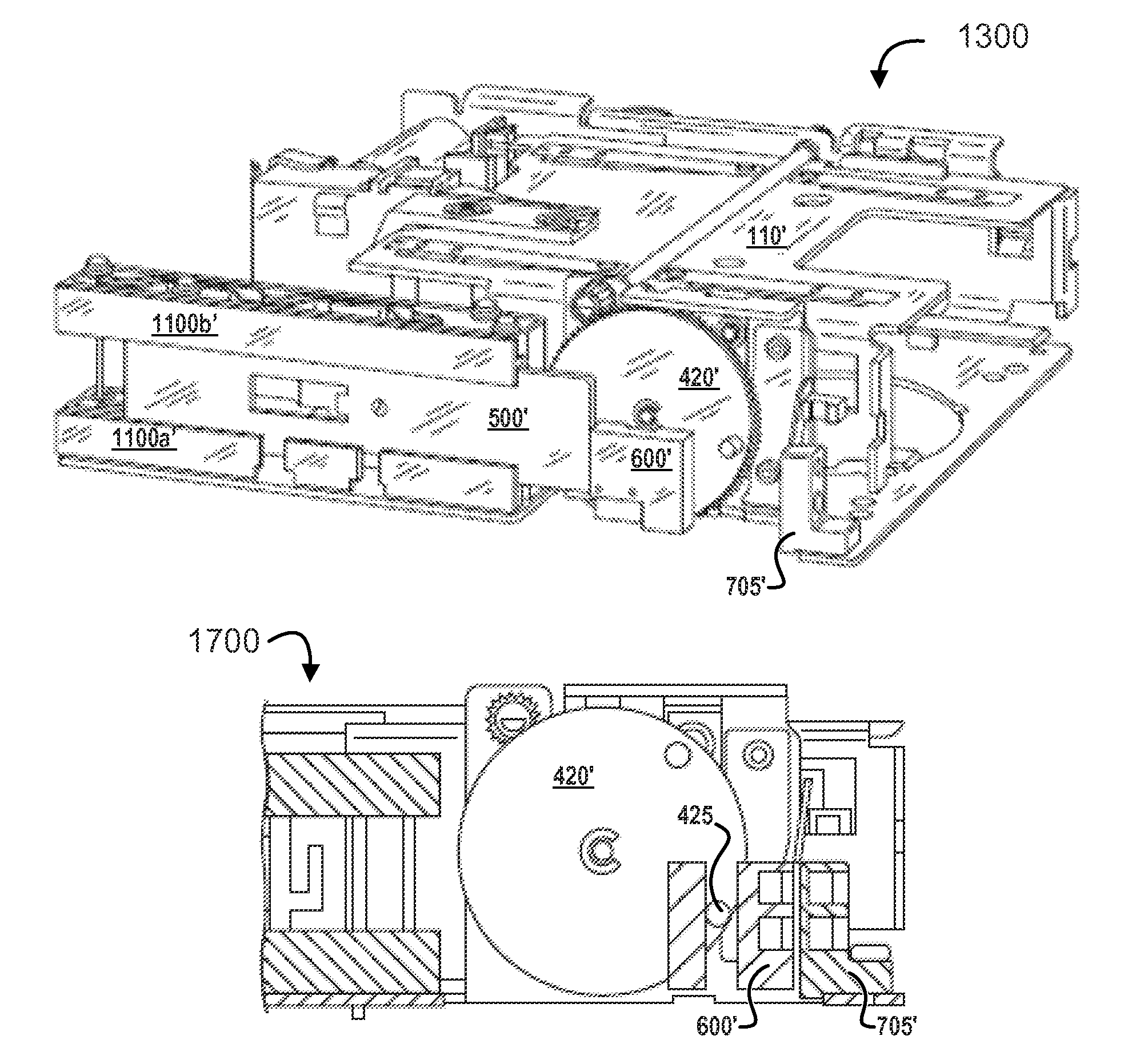
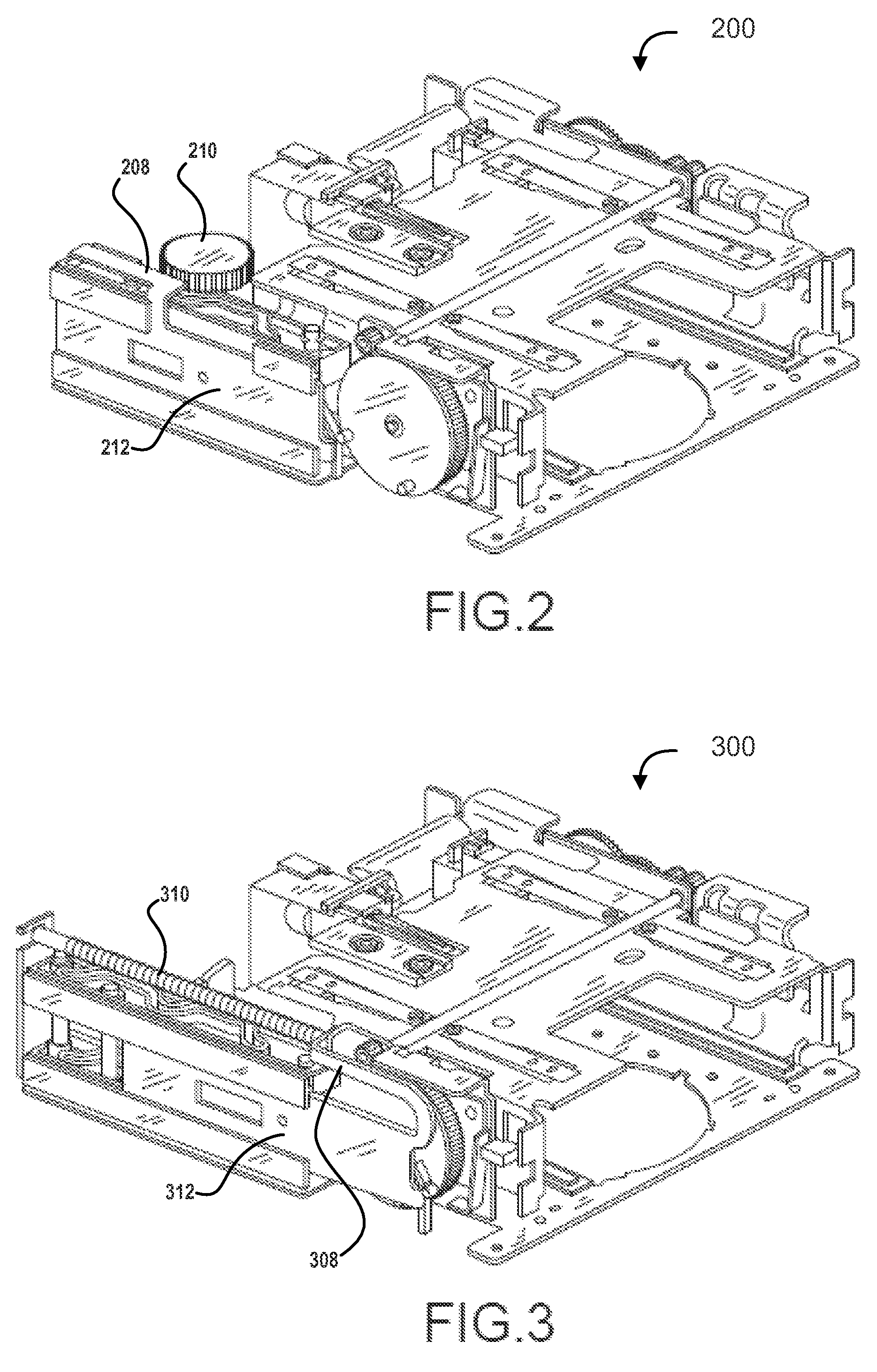
[0005]Among other things, embodiments provide novel systems and methods for buckling in a loader mechanism of a tape drive. Some embodiments are implemented in a manner that avoids use of a large-footprint tension spring, thereby permitting the footprint of the loader mechanism to be reduced. For example, the buckling forces can be provided directly by a tape drive's main motor (or another motor) via a pin interface between an elevator and a pusher plate of the loader. The pin interface can drive the pusher plate of the buckling mechanism in both forward and reverse directions. This can reduce the overall footprint of the buckler mechanism, while also lowering the torque on the drive motor and removing the spring force from the buckling mechanism. Some implementations further include a locking mechanism (e.g., implemented electrically, magnetically, and / or mechanically) that can hold the pusher plate in a “home” position without requiring a spring force.

Problems solved by technology

This can cause the magnetic tape to be pulled from the tape cartridge through the drive's tape path.

Method used


Image

  • Buckling mechanism for a tape drive loader
  • Buckling mechanism for a tape drive loader
  • Buckling mechanism for a tape drive loader

Examples


Embodiment Construction

[0037]In the following description, numerous specific details are set forth to provide a thorough understanding of the present invention. However, one having ordinary skill in the art should recognize that the invention may be practiced without these specific details. In some instances, circuits, structures, and techniques have not been shown in detail to avoid obscuring the present invention. For example, some figures include components that are intended to add clarity and context, but are not part of the inventive embodiments; while other figures show only particular components out of context to avoid over-complicating the figures. Further, while embodiments are described with reference to particular, illustrative tape drive systems, the embodiments are not intended to be limited to use of those particular tape drive systems or even particularly to magnetic recording tape.

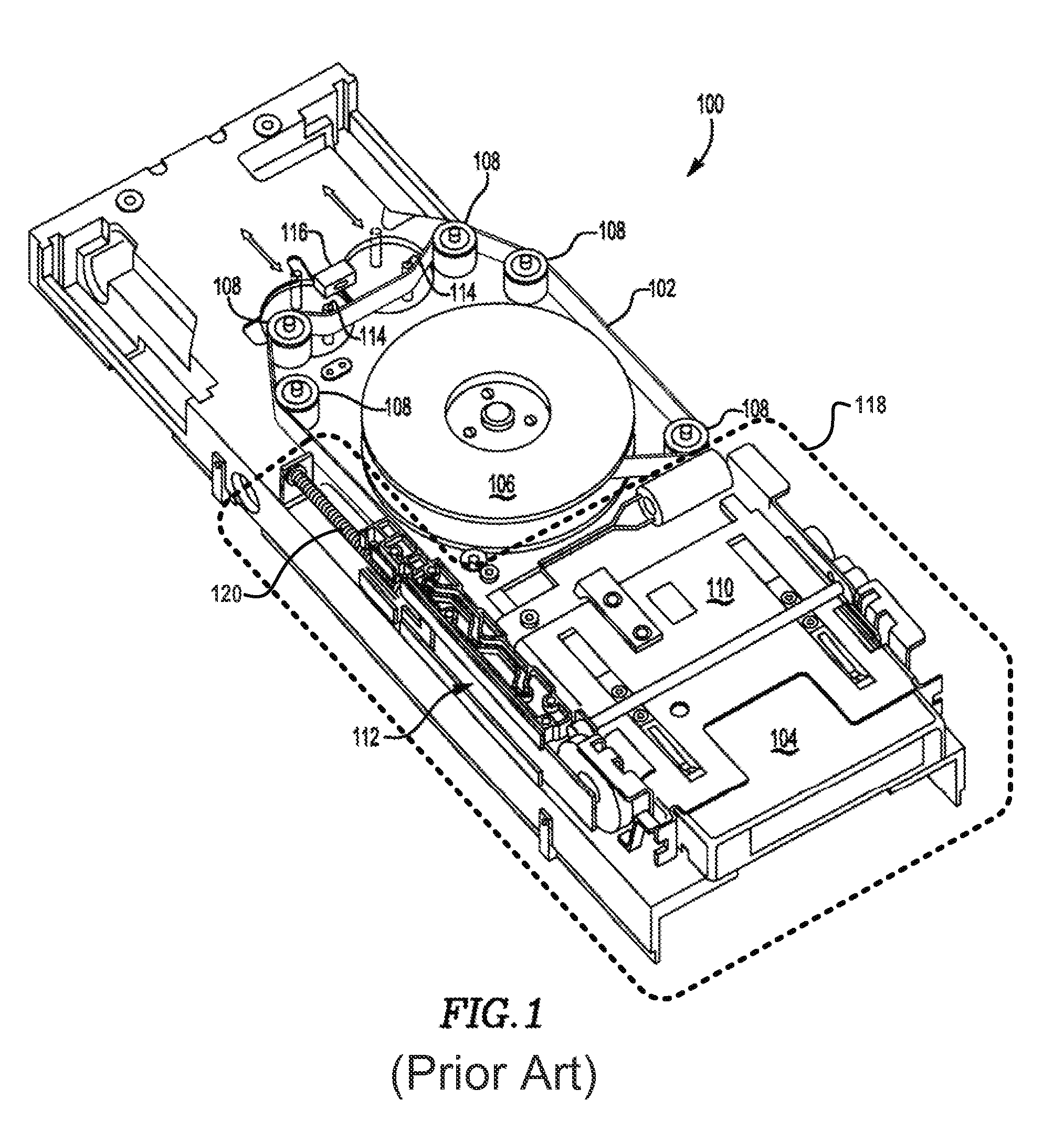
[0038]Turning first to FIG. 1, an illustrative conventional tape drive 100 is shown that uses a buckling mecha...


PUM

PropertyMeasurementUnit
forceaaaaaaaaaa
magnetic holding forceaaaaaaaaaa
mechanical holding forceaaaaaaaaaa

Abstract

Embodiments include systems and methods for buckling in a loader assembly of a tape storage drive. Some implementations translate driving forces of an elevator of the loader assembly into driving forces that act on a pusher plate of a buckling mechanism in both buckling and unbuckling directions. For example, a plate interface can couple the pusher plate with the elevator in a manner that translates rotational motion of the elevator's drive gear into a lateral driving force that drives the pusher plate between its home and buckling positions. Certain implementations also include a home holding mechanism for removably securing the pusher plate in the home position when the elevator is in its unloaded position.

Description

FIELD[0001]Embodiments relate generally to tape drives, and, more particularly, to buckling mechanisms for loader portions of tape drives.BACKGROUND[0002]Magnetic recording tape is commonly used to store digital data because magnetic recording tape is inexpensive and provides significant data storage capacity per unit volume. Consequently, magnetic recording tape remains an active component in many business operations, especially where large amounts of data must be backed-up for archival purposes. Magnetic recording tape may be housed in a tape cartridge or cassette, which protects the magnetic recording tape from damage. For example, a tape cartridge generally includes either one or two tape reels for storage of the magnetic recording tape within the tape cartridge.[0003]Data may be read from, or written to, the magnetic recording tape by inserting the tape cartridge, which contains the magnetic recording tape, into a tape drive. Tape drives typically include a tape loader mechanis...

Claims


Application Information

Patent Timeline
Patent Type & Authority Patents(United States)
IPC IPC(8): G11B15/67G11B15/675
CPCG11B15/672G11B15/674G11B15/6751Y10T74/18568
Inventor VANDERHEYDEN, WILLIAM JOSEPHHURSH, JOSHUA ADRIANOSTER, JONATHAN ZELLERMONDALE, FREDERICK PATTONBAIADA, DANIEL MARKKREMPASKY, BENJAMIN JOSEPHDERRYBERRY, WILLIAM JACOB
Owner ORACLE INT CORP
Why Eureka
Eureka Blog
Learn More