
Negative pressure device

a negative pressure and device technology, applied in the field of negative pressure devices, can solve the problems of limited negative pressure which can be maintained over the site of application, limited negative pressure duration, and system not convenient for discreet use by patients

Active Publication Date: 2015-11-10
SMITH & NEPHEW INC
View PDF39 Cites 60 Cited by
  • Summary
  • Abstract
  • Description
  • Claims
  • Application Information

AI Technical Summary

Benefits of technology

This patent aims to provide an apparatus for applying negative pressure to a wound in a cost-effective and convenient way. The apparatus can maintain negative pressure for at least ten hours without user intervention and can also provide a negative pressure within desired limits. The system includes a reduced pressure device connected to multiple negative pressure reservoirs via valves and conduits, which allows the user to select the appropriate pressure for the wound. Additionally, a safety mechanism is built into the device to prevent exposure to excessive pressures. The technical effects of this patent include prolonged application of reduced pressure at a wound site, improved vacuum performance, and better safety features.

Problems solved by technology

In common with cupping such techniques have, in the past, suffered from a very limited longevity of the therapy which can be applied.
That is to say the duration of the negative pressure which can be maintained over a site of application has been limited.
However, many of these systems are not convenient for discreet use by a patient as they are large, can be heavy and are often noisy.
Furthermore the production costs associated with such systems are substantial due largely to the cost of materials and complexity of assembly.
However, the system described does not enable prolonged convenient application of negative pressure at the wound site and in fact requires re-evacuation relatively often.
This is a serious deficiency particularly as many such systems should ideally be useable overnight.

Method used


Image

  • Negative pressure device
  • Negative pressure device
  • Negative pressure device

Examples


Embodiment Construction

[0008]It is an aim of the present invention to at least partly mitigate the above-mentioned problems.

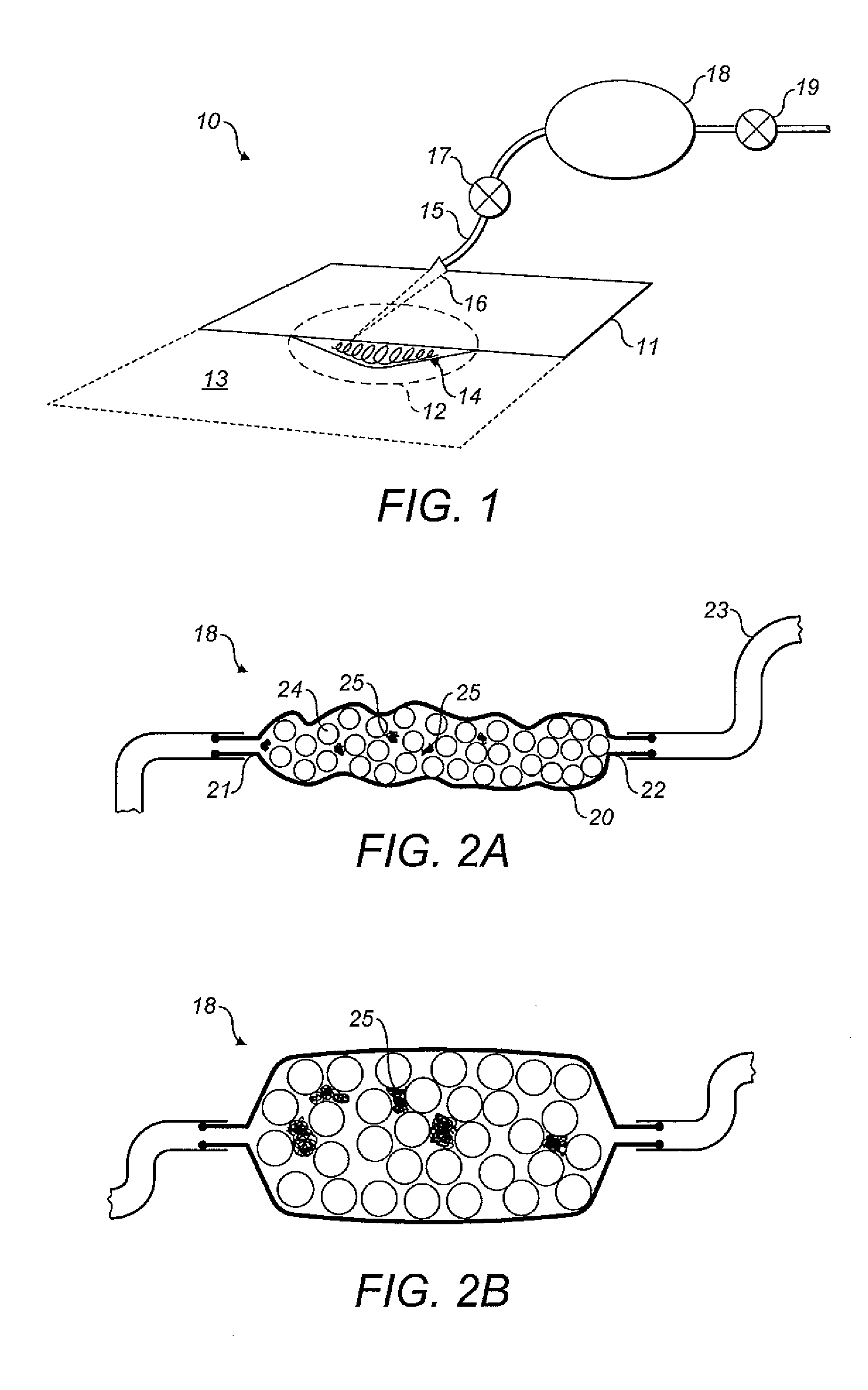
[0009]It is an aim of certain embodiments of the present invention to provide an apparatus which can be manufactured and assembled in a convenient and thus cost effective manner yet which can provide a negative pressure at a wound site within desired pressure limits over a period of time prolonged with respect to prior art techniques.

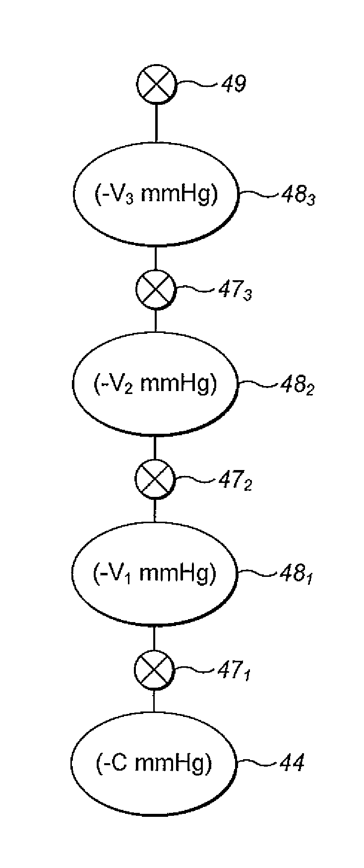
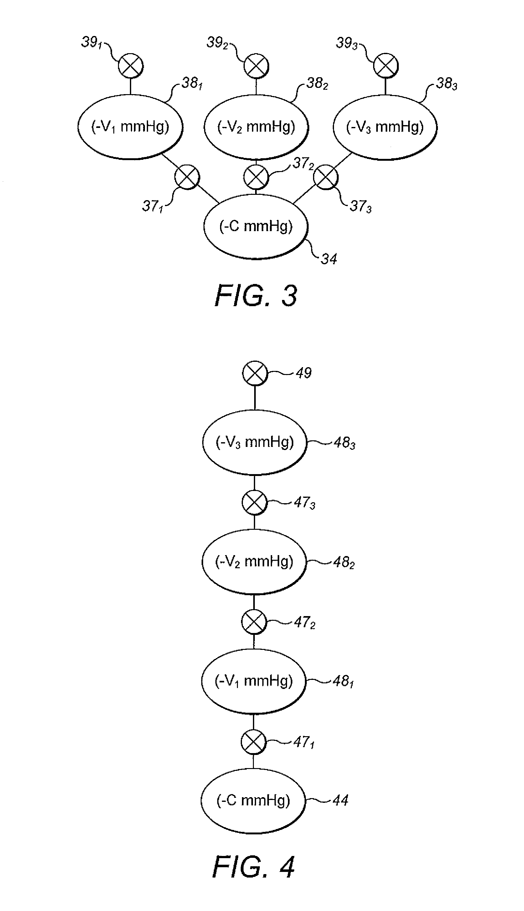
[0010]It is an aim of certain embodiments of the present invention to provide one, two or more negative pressure reservoirs or a series of negative pressure reservoirs which act as backups for the negative pressure generated at a wound site.

[0011]It is an aim of certain embodiments of the present invention to provide a system for applying negative pressure at a wound site which can remain active for at least ten hours without user interference being needed to cause re-evacuation. This enables a user to sleep undisturbed.

[0012]According to a first aspect ...


PUM


Abstract

A method and apparatus are disclosed for providing negative pressure at a wound site. The apparatus includes a negative pressure reservoir and a reservoir valve for selectively connecting the reservoir to a wound chamber at a wound site.

Description

CROSS-REFERENCE TO RELATED APPLICATIONS[0001]This application is a U.S. National Phase of PCT International Application No. PCT / GB2010 / 050020, filed on Jan. 8, 2010, designating the United States and published on Jul. 15, 2010 as WO 2010 / 079359, which claims priority to Great Britain Patent Application No. 0900423.5, filed on Jan. 12, 2009. The disclosure of both prior applications are incorporated by reference herein in their entireties and should be considered a part of this application.BACKGROUND OF THE DISCLOSURE[0002]1. Field of the Invention[0003]The present invention relates to an apparatus and method for providing negative pressure at a wound site. In particular, but not exclusively, the present invention relates to an apparatus including a source of negative pressure which acts as a negative pressure reservoir to continually or repeatedly “top up” an applied negative pressure so that negative pressure applied at a wound site can be maintained within desired limits for a rel...

Claims


Application Information

Patent Timeline
IPC IPC(8): A61H7/00A61M1/00
CPCA61M1/0031A61M1/0088A61M1/74A61M1/96A61M1/682A61M1/743
Inventor GREENER, BRYAN
Owner SMITH & NEPHEW INC
Learn More