
Method for mist control

a technology of mist control and demister, which is applied in the direction of separation process, dispersed particle separation, chemistry apparatus and processes, etc., can solve the problems of difficult removal of demisters in wet scrubbers and conventional demisters, high co and soot formation, and less attractive demisters for large gas volume applications, etc., to achieve efficient removal or substantially reduce the

Active Publication Date: 2015-11-10
AKER CARBON CAPTURE NORWAY AS
View PDF16 Cites 0 Cited by
  • Summary
  • Abstract
  • Description
  • Claims
  • Application Information

AI Technical Summary

Benefits of technology

[0018]A method for capturing CO2 from a CO2 containing gas, such as en exhaust gas from a thermal power plant fired on carbonaceous fuel, or any other CO2 containing industrial gas, where CO2 is captured from the gas by causing the gas to flow counter current to a CO2 absorbing solvent introduced into a CO2 absorption section in an absorber so that CO2 present in the gas is absorbed by the CO2 absorbing solvent to form a CO2 rich solvent, where CO2 rich solvent is collected at the bottom of the of the absorption column and withdrawn for regeneration, and where the treated exhaust gas is released to the atmosphere after being subjected to one or more washing step(s), wherein the temperature of the CO2 absorbing solvent introduced into the CO2 absorption section has a temperature that is less than 5° C. lower than the maximum temperature in the absorption section of the absorber. Mist is generated primarily during cooling of a saturated gas mixture, and is most pronounced during rapid cooling of a saturated gas mixture that includes saturation nuclei. By avoiding cooling, or at least to avoid rapid cooling of the gas mixture streaming upwards in the absorption zone of the absorber the formation of mist formed in the absorption zone is avoided or substantially reduced. Any mist formed will have a composition reflecting the composition of the condensing fluids in the gas mixture. Accordingly, any mist formed in the absorption zone will have a high content of amines or degradation products thereof. Traditionally, the absorption section of the absorber is cooled by introduction of cold CO2 solvent into the absorption zone. The temperature of the cold solvent is typically 30° C. or more, lower than the highest temperature in the absorption zone of the absorber, and the cooling is relatively abrupt at the top of the absorption zone. Reducing or even avoiding cooling of the content in the absorption zone results in a substantial reduction or avoidance of mist formation in the zone.
[0020]According to one embodiment, the treated gas leaving the absorption zone is subjected to two or more downstream washing steps where the gas is washed in counter current flow to water and wherein the washing water introduced into the first washing step has a temperature that is equal to or higher than the wet bulb temperature of the flue gas that is introduced into the washing step, to avoid cooling the gas below the wet bulb temperature and thereby avoid mist formation in the first washing step.
[0023]According to one embodiment, an acid wash section is located downstream of the washing steps in order to remove alkaline gaseous compounds such as volatile amines and ammonia, from the exhaust gas. Amines and the major degradation products thereof are basic species, and gaseous amines or degradation products thereof that is still present in the treated exhaust gas, is efficiently removed or substantially reduced by the acid wash.

Problems solved by technology

The burner was then manipulated to burn with excess fuel, resulting in high CO and soot formation.
Mist with small droplet size, when formed, is very difficult to remove in wet scrubbers and conventional demisters.
The superficial velocity through such demisters has to be very low and the pressure drop is high, making this type of demisters less attractable for large gas volume applications like power plant flue gas cleaning.
Wet electrostatic precipitator (ESP) is also proven efficient for removing mist and fine dust, but has high investment and operating cost.
Conventional processes for removal of fine and superfine particles, such as ESP and wet flue gas desulphurization (FGD) have limited efficiency in capturing particles in the sub-micron range.
As mentioned above, the investment and operating cost for wet ESP are high.
The solutions according to prior art is that they are not efficient in reducing mist following the gas that is washed.

Method used


Image

  • Method for mist control
  • Method for mist control
  • Method for mist control

Examples


Embodiment Construction

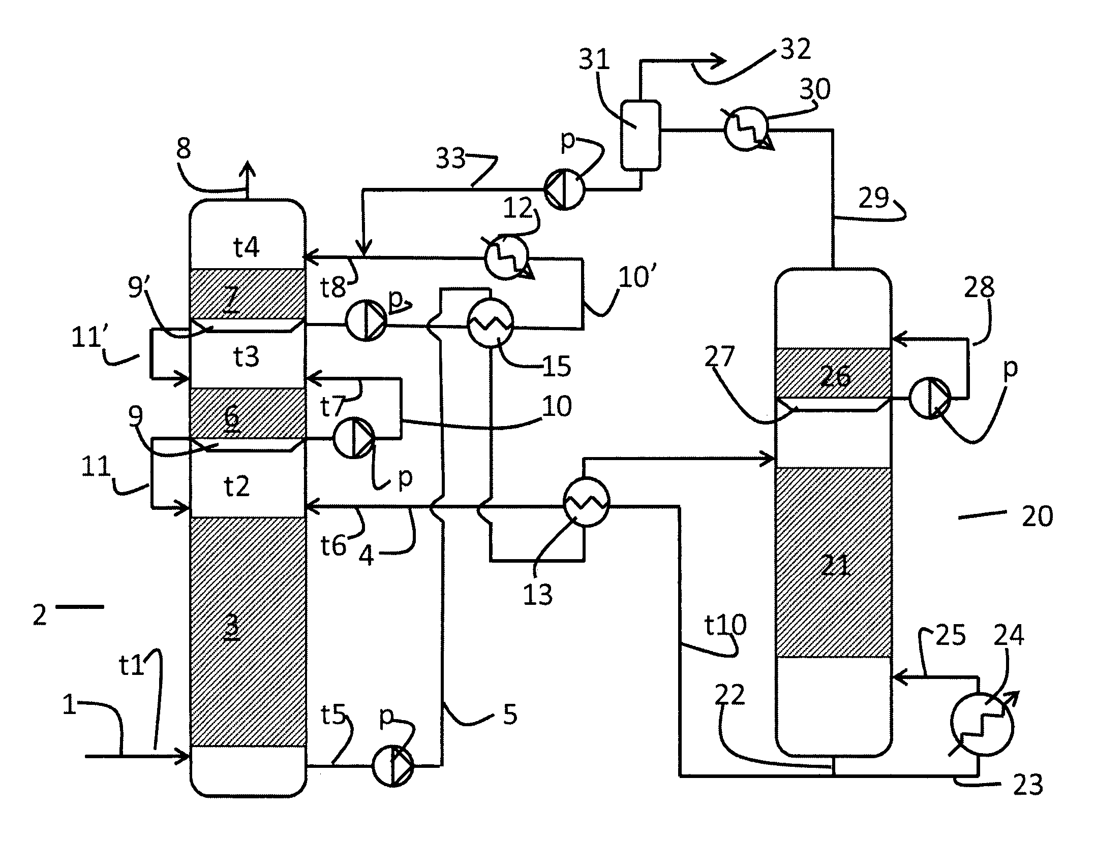
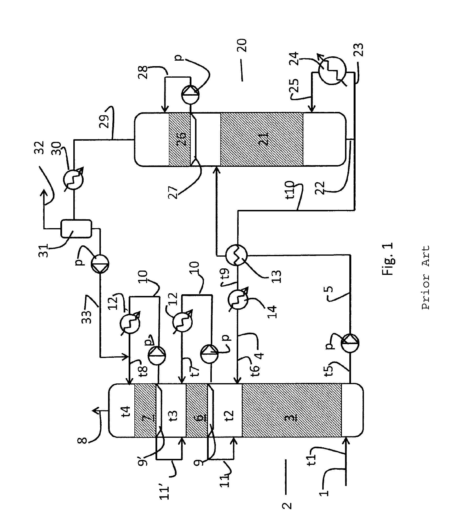
[0029]FIG. 1 illustrates a carbon capture plant according to the prior art. CO2 containing gas, such as exhaust gas from a power plant fired with carbonaceous fuel is introduced through an exhaust gas inlet 1 into an absorber 2. In the absorber 2, the exhaust gas is caused to flow countercurrent to an aqueous absorbent in a CO2 absorption section 3. The aqueous absorbent, being an aqueous solution of one or more amine(s), is introduced at the top of the CO2 absorption section 3 through a lean absorbent line 4.

[0030]Rich absorbent, having absorbed CO2, is collected at the bottom of the absorber and withdrawn through a rich absorbent line 5. The CO2 depleted flue gas leaving the CO2 absorption section 3, is then washed in one or more washing zone(s) 6, 7 to cool the flue gas, and to remove or reduce the amount of amines and degradation products from the absorbents that are carried with the flue gas. The cooled and washed exhaust gas is thereafter withdrawn from the absorber through a ...


PUM

PropertyMeasurementUnit
temperatureaaaaaaaaaa

Abstract

A method for capturing CO2 from a CO2 containing gas (1), such as en exhaust gas from a thermal power plant fired on carbonaceous fuel, or any other CO2 containing industrial gas, where CO2 is captured from the gas by causing the gas to flow counter current to a CO2 absorbing solvent introduced into a CO2 absorption section (3) in an absorber (2) so that CO2 present in the gas is absorbed by the CO2 absorbing solvent to form a CO2 rich solvent (5), where CO2 rich solvent is collected on the bottom of the of the absorption column and withdrawn for regeneration, and where the treated exhaust gas (8) is released to the atmosphere after being subjected to one or more washing step(s) (6,7), wherein the temperature of the CO2 absorbing solvent (4) introduced into the CO2 absorption section has a temperature that is less than 5° C. lower than the maximum temperature in the absorption section of the absorber, is described.

Description

TECHNICAL FIELD[0001]The present invention relates to reduction of emission of amines and amine degradation products from amine based CO2 absorbers. More specifically, the invention relates to the control of formation of mist containing amines and amine degradation products in absorbers.BACKGROUND ART[0002]A typical absorber for CO2 is a tower where exhaust gas from which CO2 is to be absorbed / removed, is brought in counter current contact with an aqueous CO2 absorbent, such as an amine, in a contact zone. The contact zone normally comprises a CO2 absorption section to increase the contact surface between the absorbent and the gas.[0003]Absorbent having absorbed CO2 is collected below the contact zone, and exhaust gas reduced in CO2 content is released from the top of the absorber.[0004]An amine based CO2 absorber is normally equipped with one or more water wash section(s) above the CO2-absorbing contact zone. The main objective of the water wash is to absorb amine vapour in order t...

Claims


Application Information

Patent Timeline
Patent Type & Authority Patents(United States)
IPC IPC(8): B01D53/14B01D53/62
CPCB01D53/1475B01D53/62B01D2252/204Y02C10/06Y02C20/40Y02A50/20
Inventor BADE, OTTO MORTENWOODHOUSE, SIMONGORSET, ODDVARANDERSSON, VIBEKE
Owner AKER CARBON CAPTURE NORWAY AS
Learn More