
Combustion Chamber and Method for Production Thereof

a combustion chamber and chamber technology, applied in the direction of soldering apparatus, shaping tools, pedestrian/occupant safety arrangements, etc., can solve problems such as the rupture of combustion chambers, and achieve the effect of high quality

Inactive Publication Date: 2010-04-29
NEUMAYER TEKFOR HLDG GMBH
View PDF25 Cites 0 Cited by
  • Summary
  • Abstract
  • Description
  • Claims
  • Application Information

AI Technical Summary

Benefits of technology

This approach ensures uniform propellant exit, enhances weld quality, and reduces the risk of chamber rupture, achieving high and stable peel strengths while maintaining economical production processes.

Problems solved by technology

It has come to light that the combustion process and the discharge of the propellant into the airbag cause injuries.
It has even occurred that the combustion chambers have been ruptured due to the pressure of the propellant.

Method used


Image

  • Combustion Chamber and Method for Production Thereof
  • Combustion Chamber and Method for Production Thereof
  • Combustion Chamber and Method for Production Thereof

Examples


Embodiment Construction

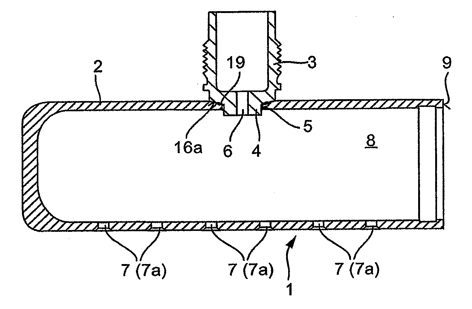
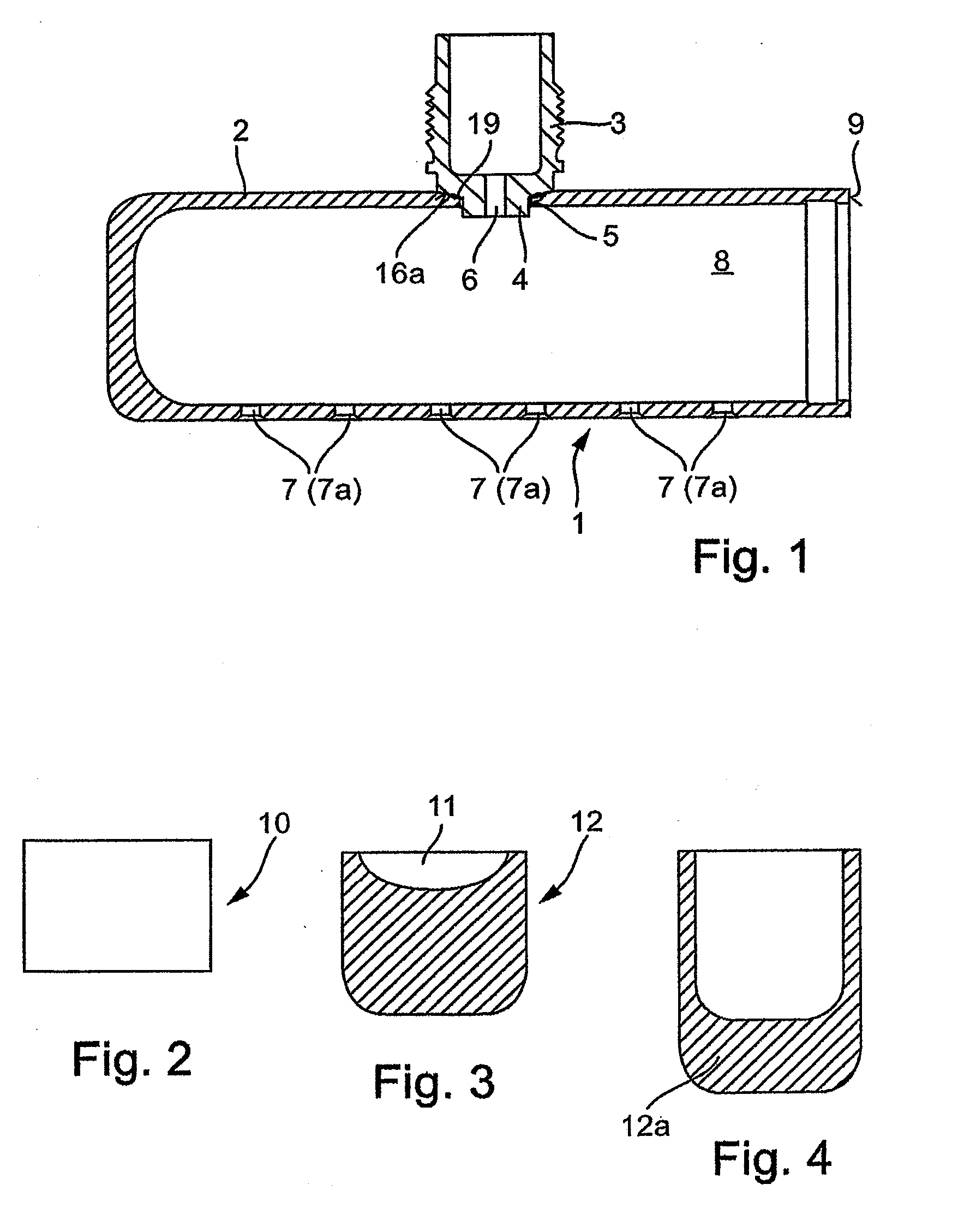
[0035]FIG. 1 shows that the combustion chamber 1 is comprised of a barrel shaped or rather sleeve shaped base body 2 with an ignition chamber 3, which is welded to said base body. The ignition chamber 3 is accommodated by inserting a neck 4 of the ignition chamber in a recess 5 of the sleeve body 2 and welding the parts together in this area. In addition, the ignition chamber 3 is provided with a transition aperture 6 and with a plurality of discharge apertures 7 (7a) on the opposite side from the transition aperture.

[0036]After the ignition chamber 3 is filled with the igniting medium and the hollow body 8 of the combustion chamber is filled with the propellant, the ignition chamber 3 is closed by means of a threaded connection, and the end face 9 of the combustion chamber is closed by welding on a cover.

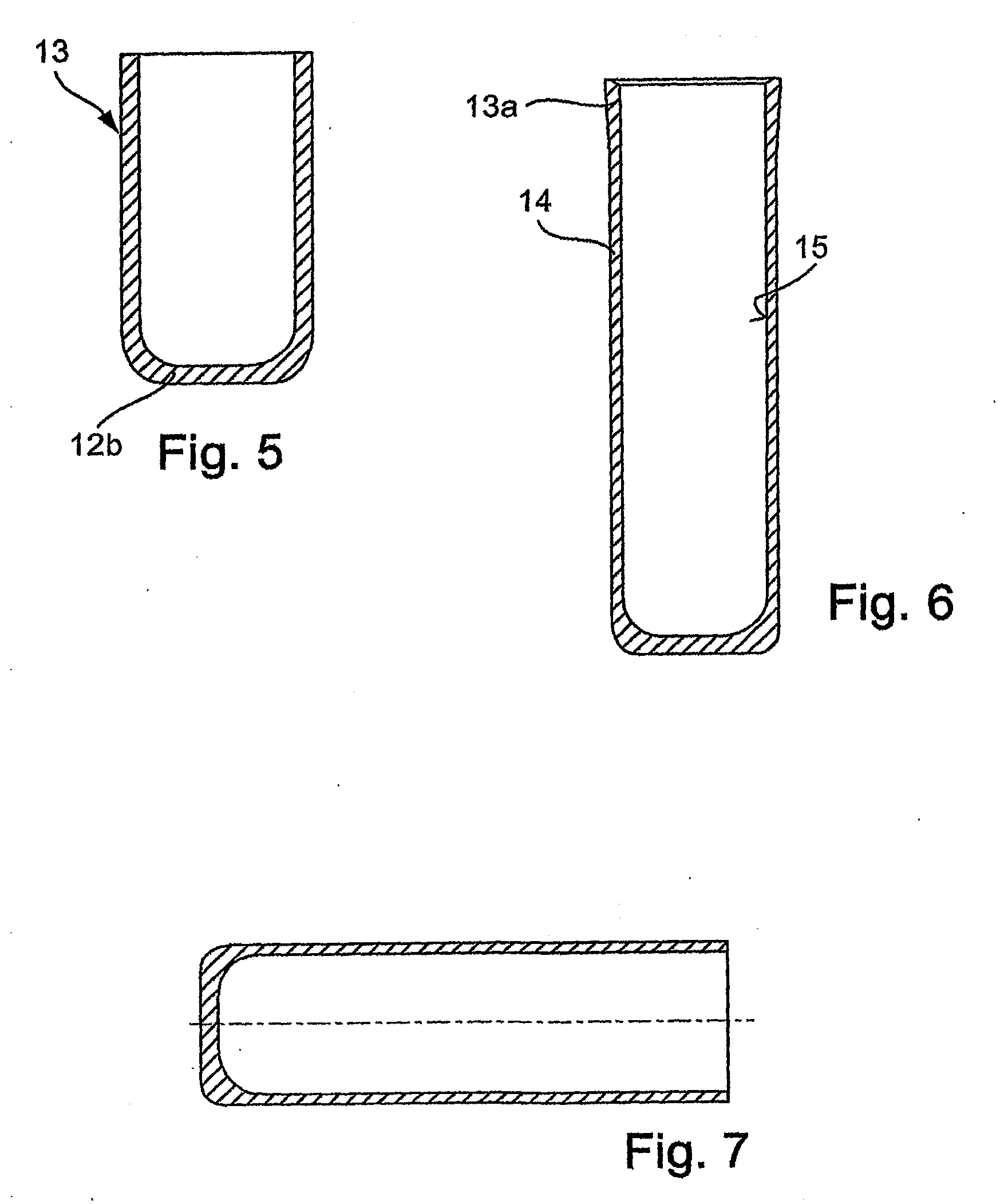
[0037]In order to produce the sleeve shaped base body of the combustion chamber, the blank 10 as shown in FIG. 2 is cut to length, for example, sawed off, from bar stock.

[0038]In a...


PUM

PropertyMeasurementUnit
thicknessaaaaaaaaaa
temperatureaaaaaaaaaa
microstructureaaaaaaaaaa

Abstract

A method for producing a combustion chamber, particularly for airbags, with a barrel shaped body to which an ignition chamber is attached by welding and which has a transition opening between the ignition chamber and the barrel shaped body and a discharge opening in the barrel shaped body lying substantially opposite the transition opening, the barrel shaped body having a wall thickness in the vicinity of the discharge opening and in the vicinity of the transition opening or of the region where the ignition chamber is attached is greater than the wall thickness of the remainder of the barrel shaped body.

Description

CROSS REFERENCE TO RELATED APPLICATIONS[0001]This application is a division of application Ser. No. 12 / 047,424, filed Mar. 13, 2008, now abandoned, which in turn was a continuation of international patent application no. PCT / DE2006 / 001579, filed Sep. 11, 2006, designating the United States of America and published in German on Mar. 22, 2007 as WO 2007 / 031057, the entire disclosures of which are incorporated herein by reference. Priority is claimed based on Federal Republic of Germany patent application nos. DE 10 2005 043 767.2, filed Sep. 13, 2005; DE 10 2006 008 581.7, filed Feb. 24, 2006, and DE 10 2006 034 285.2, filed Jul. 21, 2006.BACKGROUND OF THE INVENTION[0002]The invention relates to a barrel shaped hollow body with a mounted ignition chamber with a connecting channel between the barrel shaped body and the ignition chamber. In this case the ignition chamber serves to receive an igniting medium, which following ignition enters into the combustion chamber and ignites the pro...

Claims


Application Information

Patent Timeline
Patent Type & Authority Applications(United States)
IPC IPC(8): B23K13/01B21D37/16B23K9/00B60R21/26
CPCB21C23/205B60R21/26Y10T29/49995B60R2021/26082B60R21/264
Inventor RICHTER, WALTERMALM, STEFAN
Owner NEUMAYER TEKFOR HLDG GMBH
Learn More