

Granulator for liquid substances, particularly for urea
- Summary
- Abstract
- Description
- Claims
- Application Information
AI Technical Summary
Benefits of technology
Problems solved by technology
Method used
Image

Examples
Embodiment Construction
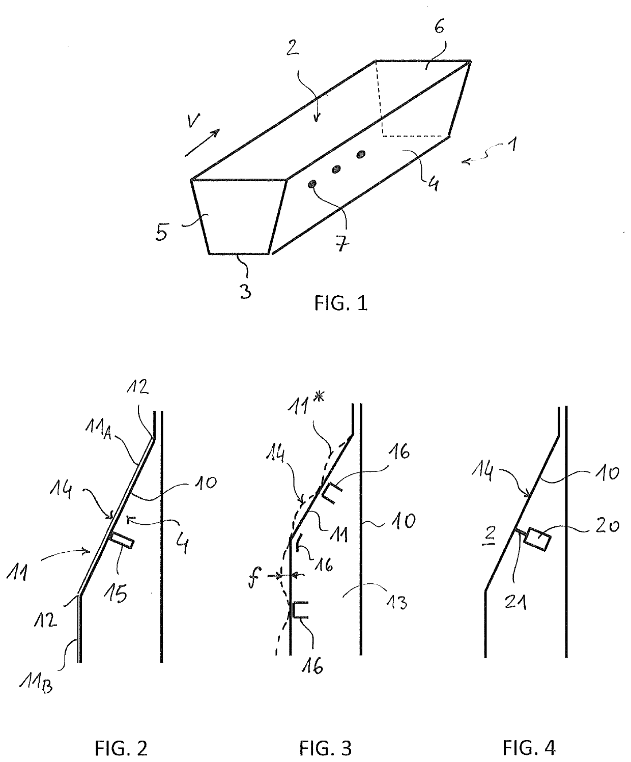
[0060]FIG. 1 shows in schematic form a urea granulator 1 which comprises a granulation chamber 2 defined by a bottom 3 and by side walls 4.
[0061]The granulator 1 has an essentially longitudinal crossing direction V from an inlet section 5 to an opposite outlet section 6. Inside the chamber 2, during operation, a fluid bed formed by the growing urea granules is created.
[0062]The granulator 1 comprises nozzles 7 which are distributed along the walls 2 and / or on the bottom 3. Said nozzles 7 spray liquid urea or highly concentrated urea solution (generally 96% or more) in order to feed the process.
[0063]Further details of the granulator 1 and the process are known to the person skilled in the art and do not need to be described for the purposes of understanding the invention.
[0064]FIG. 2 shows a schematic cross-section of a side wall 4 in a first embodiment of the invention.
[0065]Said wall 4 has a double structure comprising a load-bearing wall 10 and a membrane-type internal wall 11. T...
PUM
| Property | Measurement | Unit |
|---|---|---|
| Frequency | aaaaa | aaaaa |
| Frequency | aaaaa | aaaaa |
| Adhesivity | aaaaa | aaaaa |
Abstract
Description
Claims
Application Information