Bathtub formed of interconnected shells and method of delivering bathtubs

a bathtub and interconnected technology, applied in the field of bathtubs, can solve the problems of short glass fibers, hazardous to human health, and hazardous to the health of people in the immediate environment of the manufacturing process, and achieve the effect of reducing the cost of bathtub production

Active Publication Date: 2015-11-17
BAINS ULTRA
View PDF10 Cites 8 Cited by
  • Summary
  • Abstract
  • Description
  • Claims
  • Application Information

AI Technical Summary

Benefits of technology

[0003]It is a feature of the present invention to provide a hydromassaging bathtub formed from at least two thermoformed plastic molded shells and which eliminates fiberglass in its construction.
[0005]Another feature of the present invention is to provide a hydromassaging bathtub formed of an outer and an inner shell with the outer shell having jet forming through holes and the reinforcing support shell having channels molded in at least some of the inner side walls thereof and wherein the like shells are stacked together to reduce storage space and shipping costs and wherein the shells are assembled together only prior to shipping to customers whereby resulting in an economy in the use of floor space and providing for fast and economic delivery to customers.
[0006]Another feature of the present invention is to provide a method of delivering bathtubs having massaging jets in at least some of the side walls of the bathtub and conduits secured to at least some of the outer walls of the bathtub and which method provides various features such as faster manufacturing and delivery time, reduction in transportation costs, reduction in fabrication costs, less polluting, recyclable and provides a more healthy work environment.
[0007]Another feature of the present invention is to provide a method of delivering bathtubs wherein like shells are stacked one inside the other and shipped and stored at an assembling and distribution site and wherein the shells are assembled to form bathtubs only to supply customer demands in a designated geographical region associated with the site thereby reducing costs.
[0010]According to a further broad aspect of the present invention there is provided a method of delivering bathtubs having massaging jets in at least some of the side walls of the bathtub and conduits secured to at least some of the outer walls thereof. The method comprises forming the bathtubs from at least two thermoformed plastic molded shells at a factory with one of the shells being an outer shell having an outer finished surface, and the other of the shell being an inner reinforcing support shell shaped to receive the outer shell in close-fit therein. The outer shell is adapted to provide the massaging jets. The inner reinforcing support shell is adapted to provide conduits to the massaging jets. The method further comprises stacking a plurality of the outer shells one inside the other to form a stack of outer shells. It further comprises stacking a plurality of the inner reinforcing support shells one inside the other to form a stack of inner reinforcing support shells. The method further comprises shipping a predetermined quantity of the stacks of shells to one or more assembling and distribution sites where the outer and inner shells are stored and assembled to form the bathtubs for further shipping to supply customer demands in a designated geographical region of the one or more assembling and distribution sites and thereby reducing costs in the production of the bathtubs.

Problems solved by technology

With such spraying methods, volatile organic compounds are emitted and this is of course hazardous to the health of people in the immediate environment of the manufacturing process.
The fibers are also short glass fibers which are hazardous during the shell fabrication process and disposal.
When fabricating bathtubs with glass fiber coatings, it is necessary to test each bathtub for air and water leakages for the reason that there are often air pin holes in fiberglass coatings and this can be problematic during use.
There is also acetone released in the fiberglass coating manufacturing process and this is hazardous to human health.

Method used


Image

  • Bathtub formed of interconnected shells and method of delivering bathtubs
  • Bathtub formed of interconnected shells and method of delivering bathtubs
  • Bathtub formed of interconnected shells and method of delivering bathtubs

Examples


Embodiment Construction

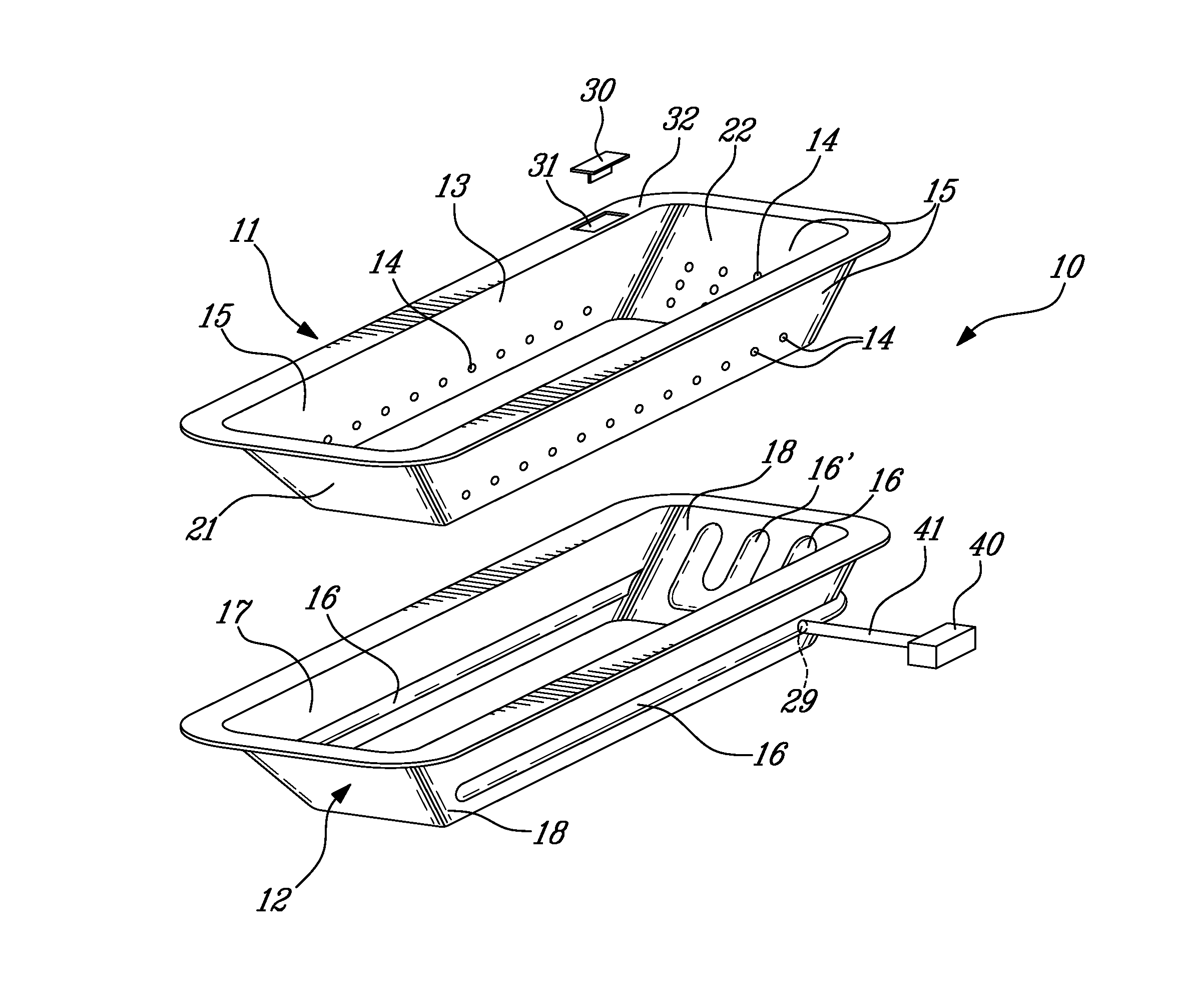
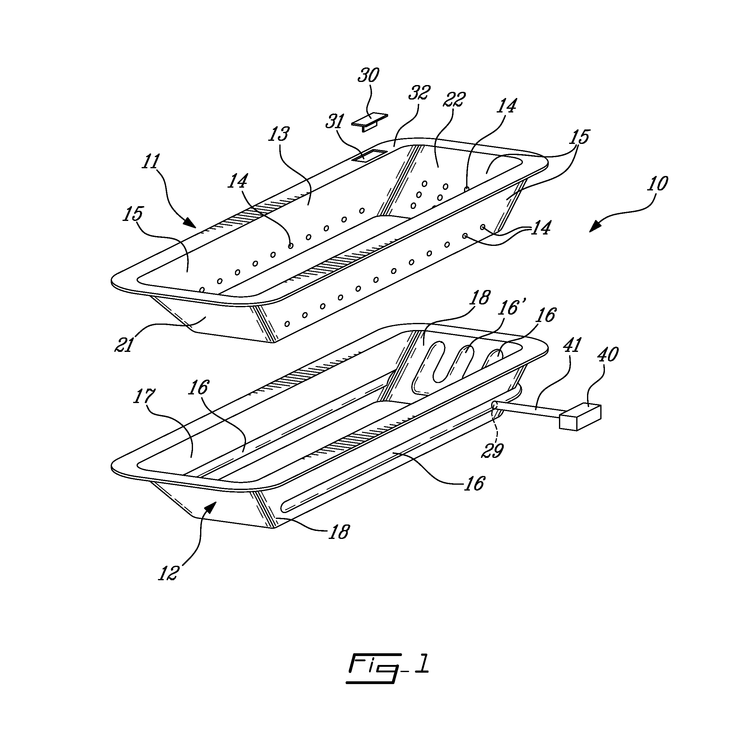
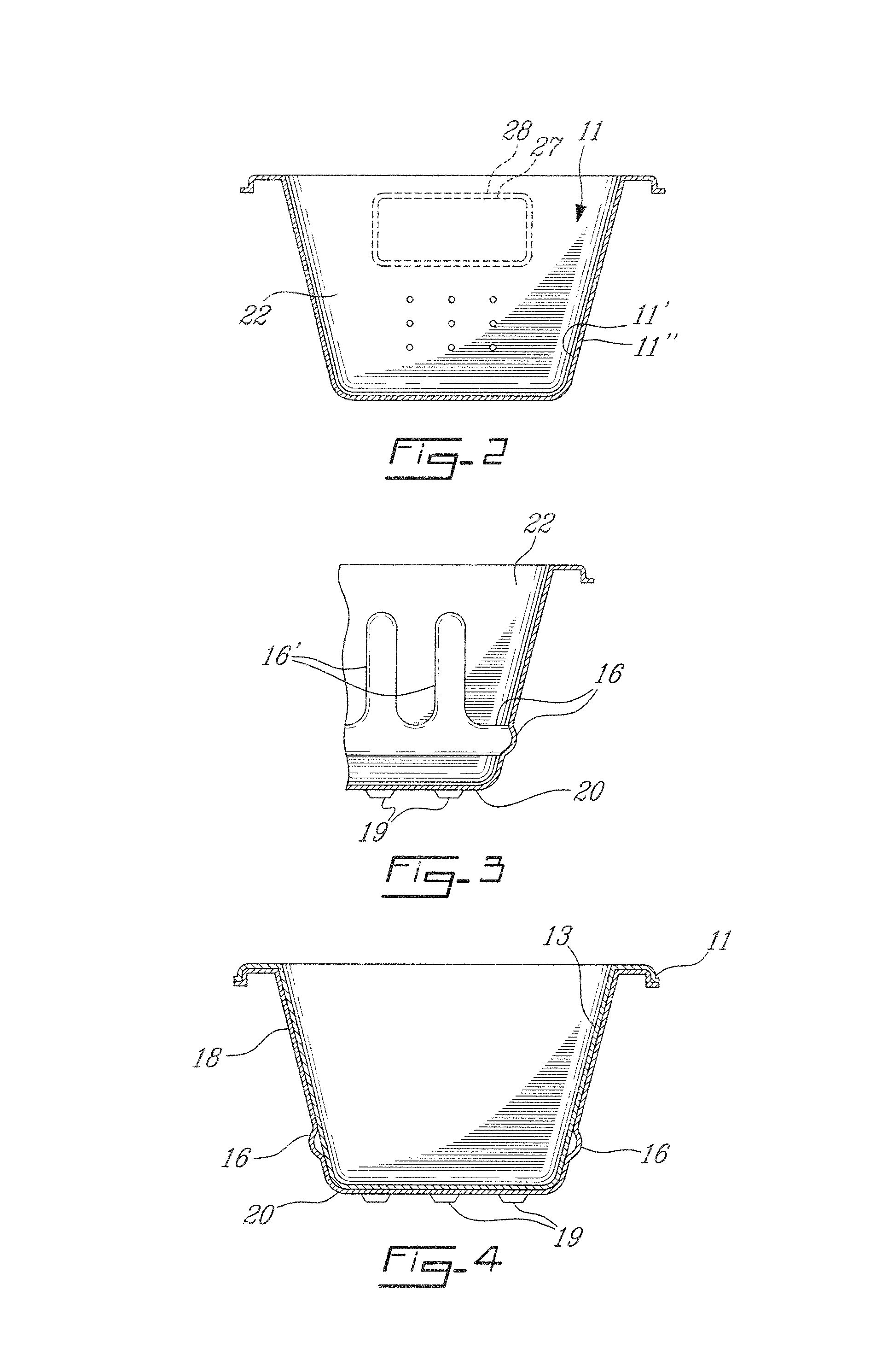
[0019]Referring now to the drawings and more particularly to FIGS. 1 to 4, there is shown generally at 10, in FIG. 1, a hydromassaging bathtub formed in accordance with the present invention. As shown in these drawings, the bathtub 10 is formed from at least two thermoformed plastic molded shells, herein an outer shell 11 and an inner reinforcing support shell 12. The outer shell 11 has an outer finish surface 13 which has an acrylic component therein to provide a smooth and shiny outer surface comfortable to a bather person and hygienic. It also has a plurality of air jet forming through holes 14 disposed in a predetermined pattern in at least some surrounding side walls 15 thereof. These through holes 14 are of predetermined diameter and drilled at specific spacing and pattern.

[0020]The inner reinforcing support shell 12 is also thermoformed from a single sheet of plastic material having a desired amount of rigidity and it is shaped to receive the outer shell 11 in close fit there...


PUM

PropertyMeasurementUnit
diameteraaaaaaaaaa
pressureaaaaaaaaaa
volatileaaaaaaaaaa

Abstract

A hydromassaging bathtub is formed by molding an outer shell having an outer finished surface with an acrylic component therein and a plurality of air jets forming through holes, and an inner reinforcing support shell having channels molded in at least some of the inner side walls thereof. The inner shell has floor supports molded in a bottom wall thereof. The outer shell is bonded in the inner shell with the channels sealingly bonded about the plurality of air jet forming through holes. The method comprises stacking the similar shells together for shipping to an assembling and distribution site and for storage whereby to provide several commercial advantages in the manufacture and distribution of the bathtubs.

Description

TECHNICAL FIELD[0001]The present invention relates to the manufacture and commercialization of bathtubs, and particularly but not exclusively, to hydromassaging bathtubs formed of at least two molded shells and incorporating jets and conduits formed in the manufacture thereof.BACKGROUND ART[0002]It is known to fabricate bathtubs and the like by thermoforming rigid thermoplastic shells and bonding the shells together such as described in U.S. Pat. No. 5,494,718. As described in that patent, it is desirable to eliminate methods using spraying techniques which are essentially manual in the formation of bathtubs and wherein a curing period is desirable. With such spraying methods, volatile organic compounds are emitted and this is of course hazardous to the health of people in the immediate environment of the manufacturing process. That patent is primarily concerned with the reduction in the wall thickness of a thermoformed vessel by the use of a reinforced cradle. They attempt to elimi...

Claims


Application Information

Patent Timeline
Patent Type & Authority Patents(United States)
IPC IPC(8): A61H33/06A47K3/00B29C51/26B29L31/00
CPCA47K3/00A61H33/06B29C51/266B29L2031/7692Y10T29/49826
Inventor BRUNELLE, HENRY
Owner BAINS ULTRA
Why Eureka
Try Eureka