Electric vehicle carousel battery exchange/charging system

a technology for electric vehicles and charging systems, applied in secondary cells, battery servicing/maintenance, electrochemical generators, etc., can solve the problems of limited mobility of electric vehicles, inability to be used by drivers when driving long distances or taking a vacation, etc., to increase the demand for electric vehicles, convenient and convenient location, and convenient and convenient us

Inactive Publication Date: 2015-11-17
DAVIS HAROLD WILLIAM
View PDF15 Cites 62 Cited by
  • Summary
  • Abstract
  • Description
  • Claims
  • Application Information

AI Technical Summary

Benefits of technology

[0008]An object of the present invention is to increase the public's demand for using electric vehicles.
[0009]Another object of the present invention is to provide owners of electric vehicles with the ability to exchange their vehicles' depleted electrical batteries, no matter what size or type, for charged electrical batteries.
[0010]Yet another object of the present invention is to provide service stations that can process the battery exchanges in as little time as the task of re-fueling a vehicle's gas tank, making such exchanges both easy and convenient.
[0011]A still further object of the present invention is to provide service stations that can charge depleted batteries so that they are ready for reinstallation into another electric vehicle.
[0012]One more object of the present invention is to provide a system and service stations which can be conveniently located on highways, thereby improving the mobility of electric vehicles.

Problems solved by technology

The widespread adoption of vehicles powered by electrical batteries has been impeded by their limited mobility.
While the vehicle serves its purpose for commuting and for local trips, presently it cannot be depended upon by a driver to use when driving long distances or when taking a vacation away from home.

Method used


Image

  • Electric vehicle carousel battery exchange/charging system
  • Electric vehicle carousel battery exchange/charging system
  • Electric vehicle carousel battery exchange/charging system

Examples


Embodiment Construction

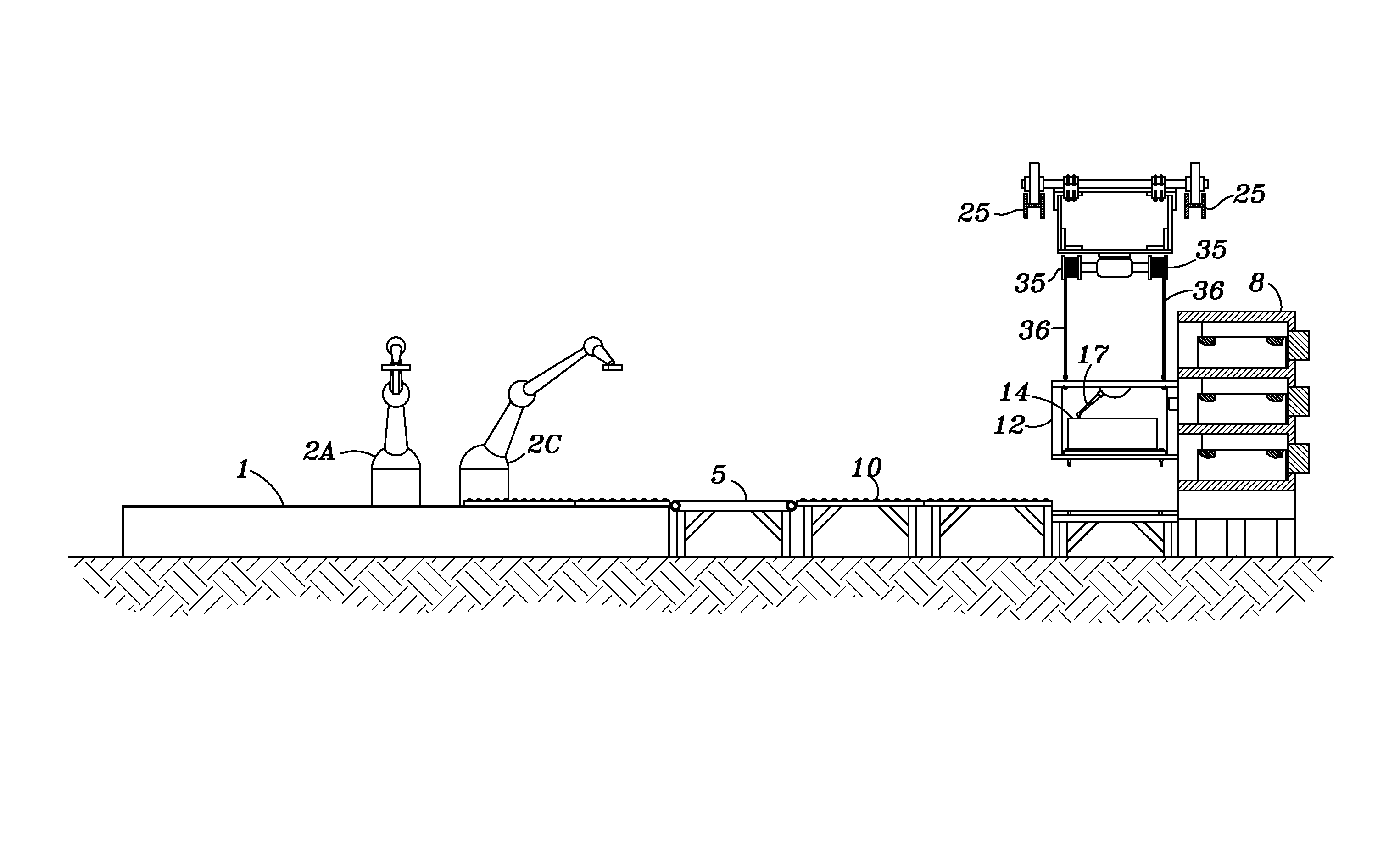
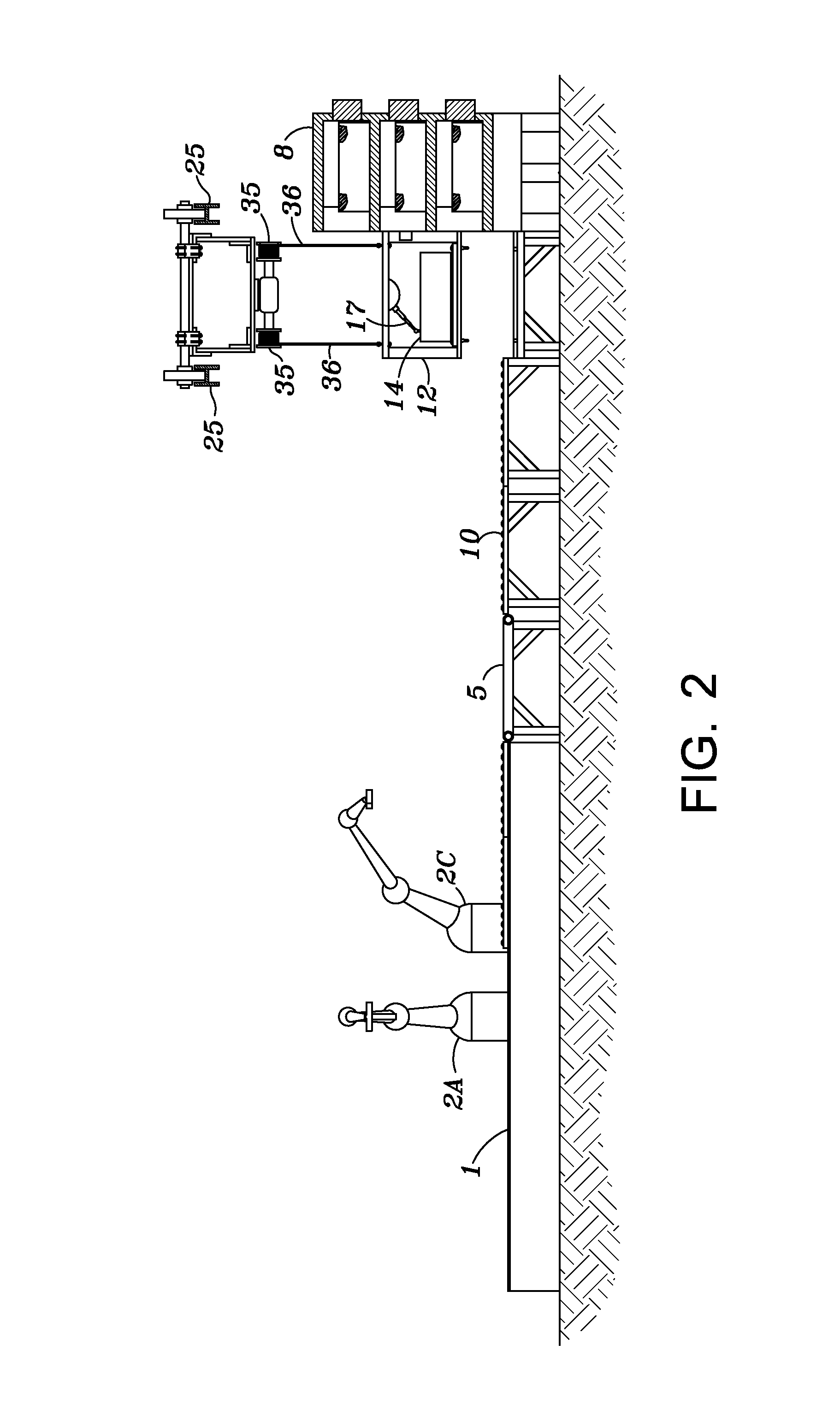
[0031]The system of the present invention is designed to incorporate a linear movement of a depleted battery from the time it is removed from a vehicle until the time, after re-charging, that it is re-introduced into a similar electric vehicle.

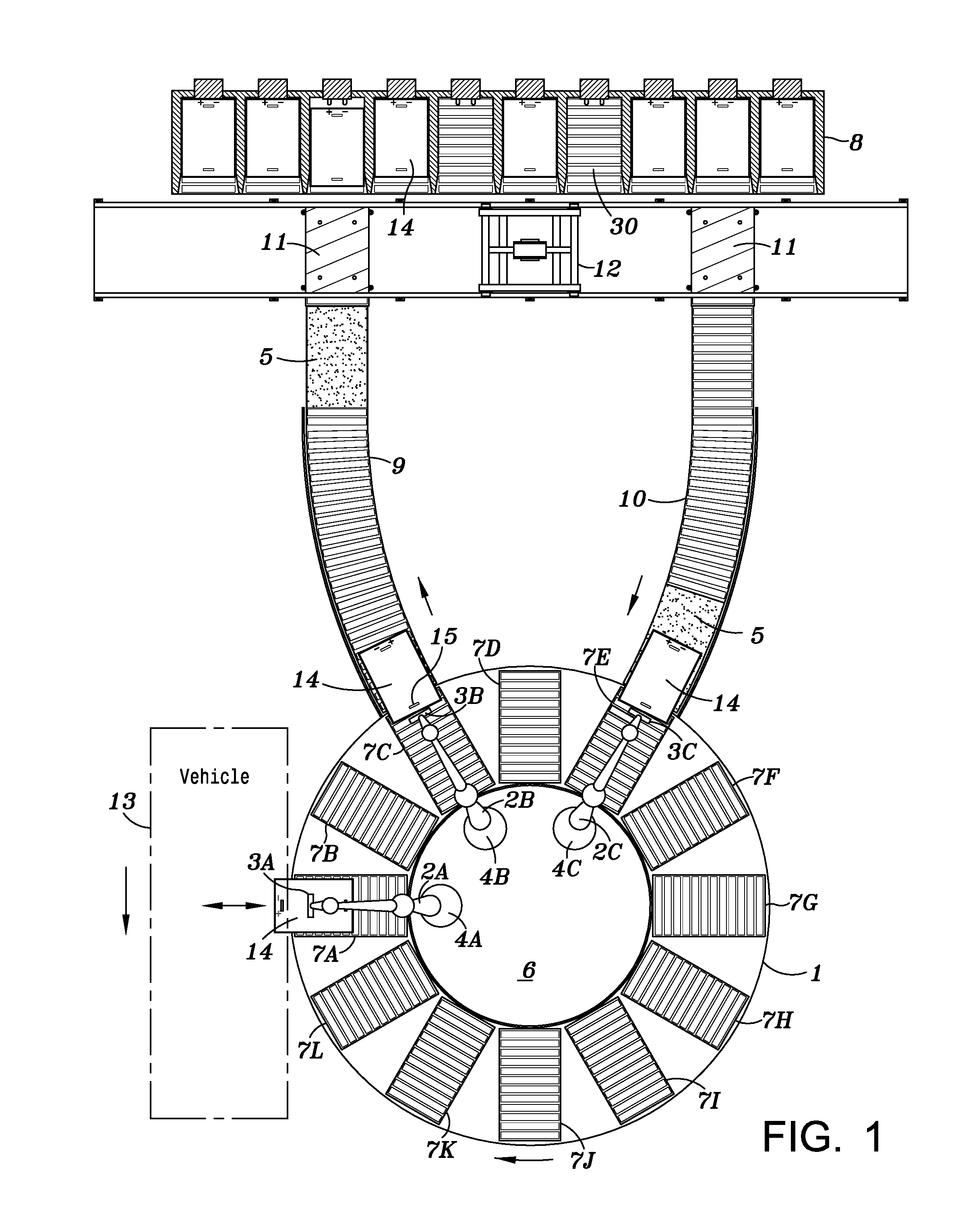
[0032]As shown in FIG. 1, the exchange / charging system of the present invention comprises a horizontal, circular, rotating carousel 1 with an even number of rectangular roller conveyor sections 7 (here shown as 7A, 7B, 7C, 7D, 7E, 7F, 7G, 7H, 71, 7J, 7K, and 7L). A stationary circular platform 6 supports several pedestals 4 (here 4A, 4B, and 4C), each of which holds a robotic / mechanical arm 2 (here 2A, 2B, and 2C). There will be three or four robotic / mechanical arms 2, depending on the configuration of the system. The robotic / mechanical arms 2 are used to either remove or install a battery 14 from or into an electric vehicle 13, using its blade 3 (here 3A, 3B, and 3C), which is inserted into the slot 15 of the battery 14. The batteries 14 are ...


PUM

PropertyMeasurementUnit
vertical movementaaaaaaaaaa
circumferenceaaaaaaaaaa
distanceaaaaaaaaaa

Abstract

A system providing a driver of an electric vehicle with the ability to exchange a depleted battery with a charged battery. Information regarding the status of an electric battery is transmitted to service stations, and information is returned to a driver indicating the location of a service station with a charged battery. The driver enters the station and is automatically positioned next to a rotating carousel. A robotic arm removes the depleted battery from the vehicle and pulls it onto the carousel, which rotates and deposits the battery onto a return conveyor belt, which carries the battery to a transportation platform for movement to a battery rack for charging. The transportation platform removes a charged battery from the battery rack and carries it to an outgoing conveyor belt, which carries it to the carousel, which rotates until the battery is next to the vehicle for insertion by the robotic arm.

Description

FIELD OF THE INVENTION[0001]The present invention relates to a system that can be implemented in roadside stations to enable owners of electrically-powered vehicles to exchange depleted or discharged batteries with charged batteries, thereby improving their mobility.BACKGROUND OF THE INVENTION[0002]The widespread adoption of vehicles powered by electrical batteries has been impeded by their limited mobility. An owner can use an electrically-powered vehicle (hereinafter “electric vehicle”) to drive to work, to shop, and to perform errands, but he must keep in mind his distance from his power source, which is typically his garage. The vehicle's battery is plugged into the home's power source in the evening so that it can be charged overnight. While the vehicle serves its purpose for commuting and for local trips, presently it cannot be depended upon by a driver to use when driving long distances or when taking a vacation away from home.[0003]A need exists for roadside stations which e...

Claims


Application Information

Patent Timeline
Patent Type & Authority Patents(United States)
IPC IPC(8): H01M10/46B60L11/18B60S5/06
CPCB60L11/1822B60S5/06B60L11/1824H01M10/42H01M2010/4278H01M2220/20B60L53/80B60L53/30Y02T90/12Y02T10/70Y02T10/7072Y02E60/10
Inventor DAVIS, HAROLD WILLIAM
Owner DAVIS HAROLD WILLIAM
Why Eureka
Try Eureka