Angle configuring stabilizing assembly for extension ladders

a technology of stabilizing assembly and extension ladder, which is applied in the direction of ladders, building construction, construction, etc., can solve the problems of not being able to prevent slippage or bending, and the system is not practical with long extension ladders. to achieve the effect of maximum stability

Active Publication Date: 2015-11-17
PARSONS ANDREW S
View PDF35 Cites 12 Cited by
  • Summary
  • Abstract
  • Description
  • Claims
  • Application Information

AI Technical Summary

Benefits of technology

[0013]The present invention provides a fully adjustable ladder stabilizer assembly for extension ladders. The stabilizer legs and the lower braces can be attached to the ladder through any hollow rung. Special joints enable the legs to extend back and to the sides of the rails over a substantial arc to enable maximum stability. The adjustability of both the legs and the braces permit the ladder to be used and fully supported at the recommended angle range of 72° to 75.5°. The legs and braces are calibrated to assist in attaining the recommended angle.

Problems solved by technology

These devices are usually attached to the lower portion of the ladder rails and do not prevent slippage or bending due to weight bearing.
This system is not practical with long extension ladders.
The hook connectors, though enabling a three-point connection, are open and do not appear sufficient to hold the system together under the stress of repeated use.
This system appears to be very flimsy and the legs cannot move laterally.
These holes can weaken the rails and damage the integrity of the ladder thereby interfering with the manufacturer's requirements to comply with statutory safety specifications.

Method used


Image

  • Angle configuring stabilizing assembly for extension ladders
  • Angle configuring stabilizing assembly for extension ladders
  • Angle configuring stabilizing assembly for extension ladders

Examples


Embodiment Construction

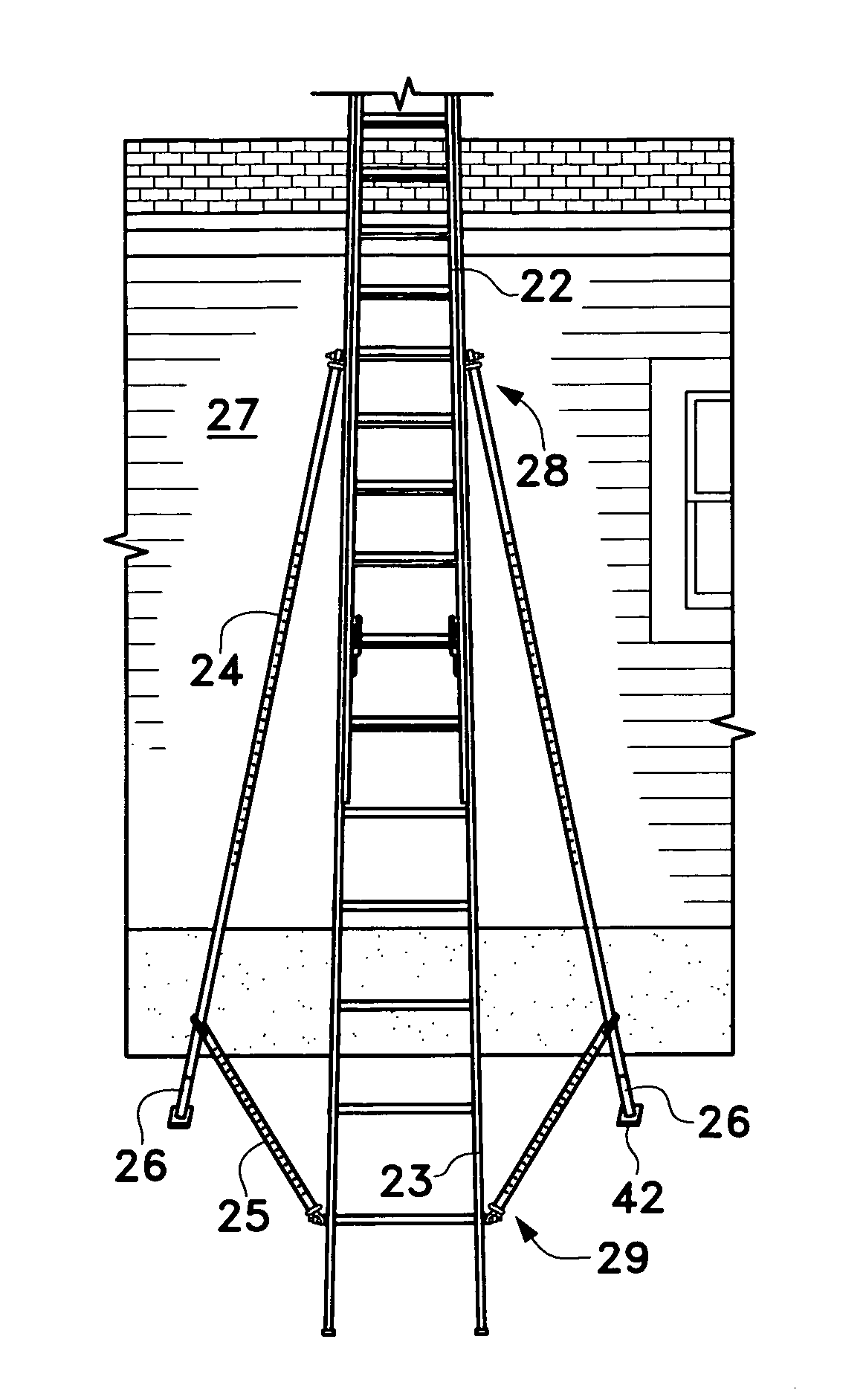
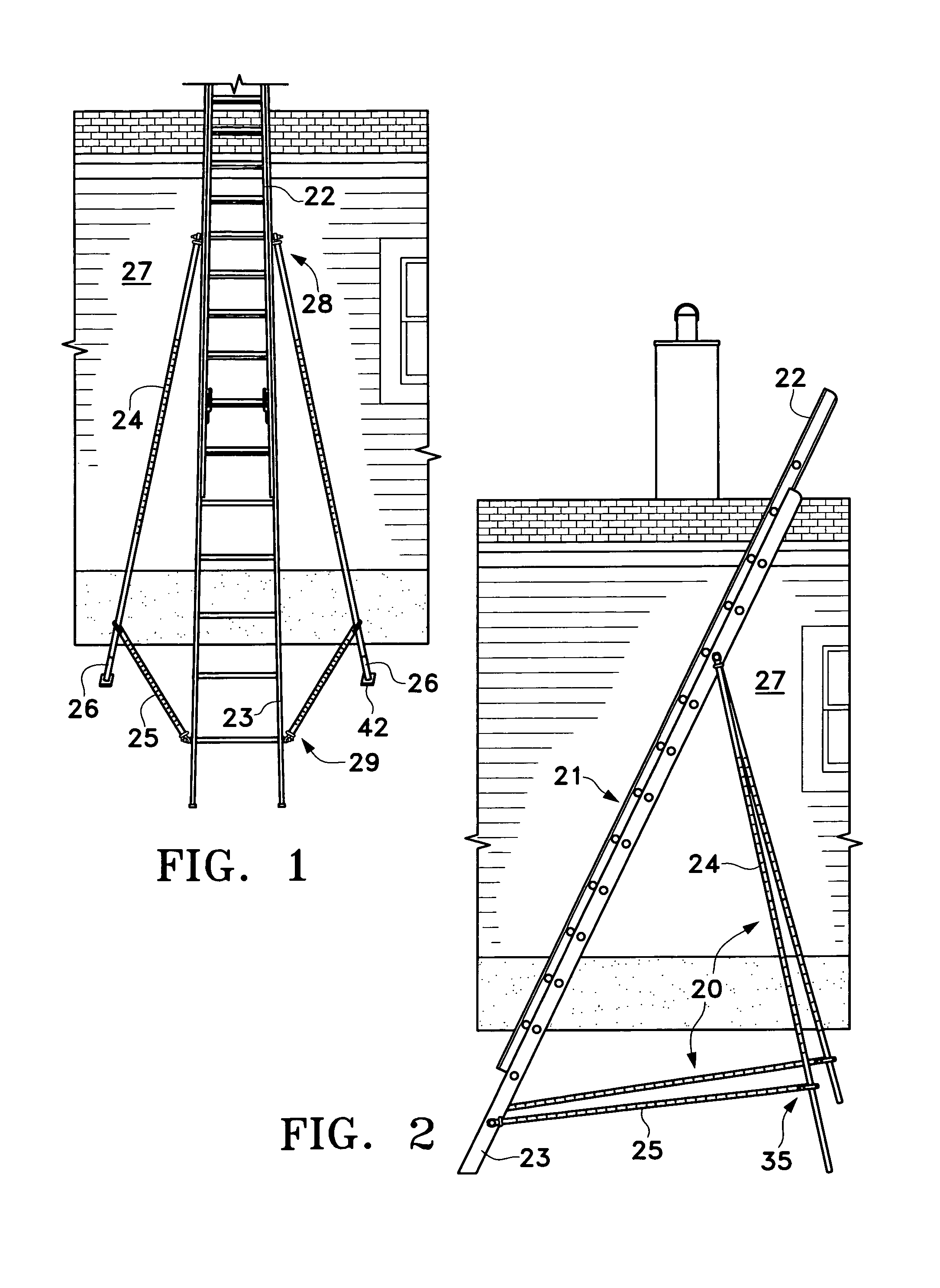
[0038]The ladder stabilizing assembly 20 of the present invention may be used with any conventional extension ladder 21 being composed of two segments, each having parallel side rails and a series of hollow rungs placed at regular intervals between the rails. The assembly 20 may support the ladder 21 from any point along its length, but optimum performance may be obtained when the attachment is made at a point that is substantially the midpoint of the working length L of the ladder. The working length L of the ladder is defined as the distance along the ladder between the foot and the top support.

[0039]The assembly 20 is made up of two identical support components attached at opposing sides of the ladder 21. The two components are each composed of an adjustable length leg 24 and an adjustable length brace 25. There may be an extension 26 at the bottom of each leg 24 to enable proper adjustment when the ground is not even, with a slip resistant foot 42 at the base of each extension 2...


PUM


Abstract

A ladder stabilizing assembly for extension ladders has two length adjustable legs attached to opposing sides of the ladder at substantially the midpoint of the working distance of the ladder and two length adjustable braces attached to opposing sides of the ladder near the bottom and are securely attached to the legs. Rods through the hollow rungs attach the legs and braces to the ladder. Heim joints at one end of each leg and brace attach securely to the rods and enable the legs and braces to pivot and swivel for optimum stability placement. The ladder and stabilizer function as a single unit with a wide four point base. The legs and braces are calibrated to assist in setting the ladder at the standard angle for safe use. The stabilizing assembly prevents the ladder from sliding, tipping or other movement and enables the user to work wearing a safety harness.

Description

[0001]This application discloses substantially the same invention disclosed in Provisional Patent Application Ser. No. 61 / 205,968 filed on Jan. 26, 2009.FIELD OF THE INVENTION[0002]The instant invention relates to a stabilizer assembly for extension ladders that prevents lateral movement and tipping, prevents the bottom of the ladder from sliding outward from the vertical supporting structure, further prevents weight bearing distortion, and enables setting the ladder at the proper recommended angle for optimum performance and safety.BACKGROUND OF THE INVENTION[0003]Ladder accidents are some of the most preventable in the building and construction industry. There have been a number of devices developed to prevent ladders from being displaced from their setting during use. Many of these attach to the sides of the ladder and provide lateral support. These devices are usually attached to the lower portion of the ladder rails and do not prevent slippage or bending due to weight bearing. ...

Claims


Application Information

Patent Timeline
Patent Type & Authority Patents(United States)
IPC IPC(8): E06C7/42E06C7/48
CPCE06C7/48E06C1/12E06C1/22E06C7/423
Inventor PARSONS, ANDREW S.
Owner PARSONS ANDREW S
Why Eureka
Try Eureka