
Current monitor and electric power quality compensation system

a technology of compensation system and current monitor, which is applied in the direction of voltage/current isolation, power supply testing, instruments, etc., can solve the problems of limiting the selective scope of the current monitor, deteriorating the compensation effect of the compensation module, and following problems of the conventional current monitor

Active Publication Date: 2015-11-17
DELTA ELECTRONICS INC
View PDF11 Cites 0 Cited by
  • Summary
  • Abstract
  • Description
  • Claims
  • Application Information

AI Technical Summary

Benefits of technology

[0014]an isolation and transfer module including an input side and an output side electrically isolated from each other, wherein the input side is configured to be connected with the external detection module, the output side is configured to be connected with the internal monitor module, and the isolation and transfer module receives the first level detection current and outputs a second level detection current to the internal monitor module so as to reduce the impedance of the internal monitor module reflected to the external detection module.
[0019]an isolation and transfer module including an input side and an output side electrically isolated from each other, wherein the input side is configured to be connected with the external detection module, the output side is configured to be connected with the internal monitor module, and the isolation and transfer module receives the first level detection current and outputs a second level detection current to the internal monitor module so as to reduce the impedance of the internal monitor module reflected to the external detection module;
[0021]In the embodiments of the present application, the isolation and transfer module is added into the current monitor and outputs a second level detection current to the internal monitor module based on a first level detection current received from the external detection module 1, and thus plays a role of reducing the equivalent impedance of the internal monitor module reflected to the external detection module. Accordingly, it's possible to avoid the output-side load of the external detection module from going beyond its output-side capacity. In another aspect, the isolation and transfer module may be adjusted in its parameters so as to adjust its ability of impedance reduction, thereby no restriction of the geographical location or selective scope of the current monitor.

Problems solved by technology

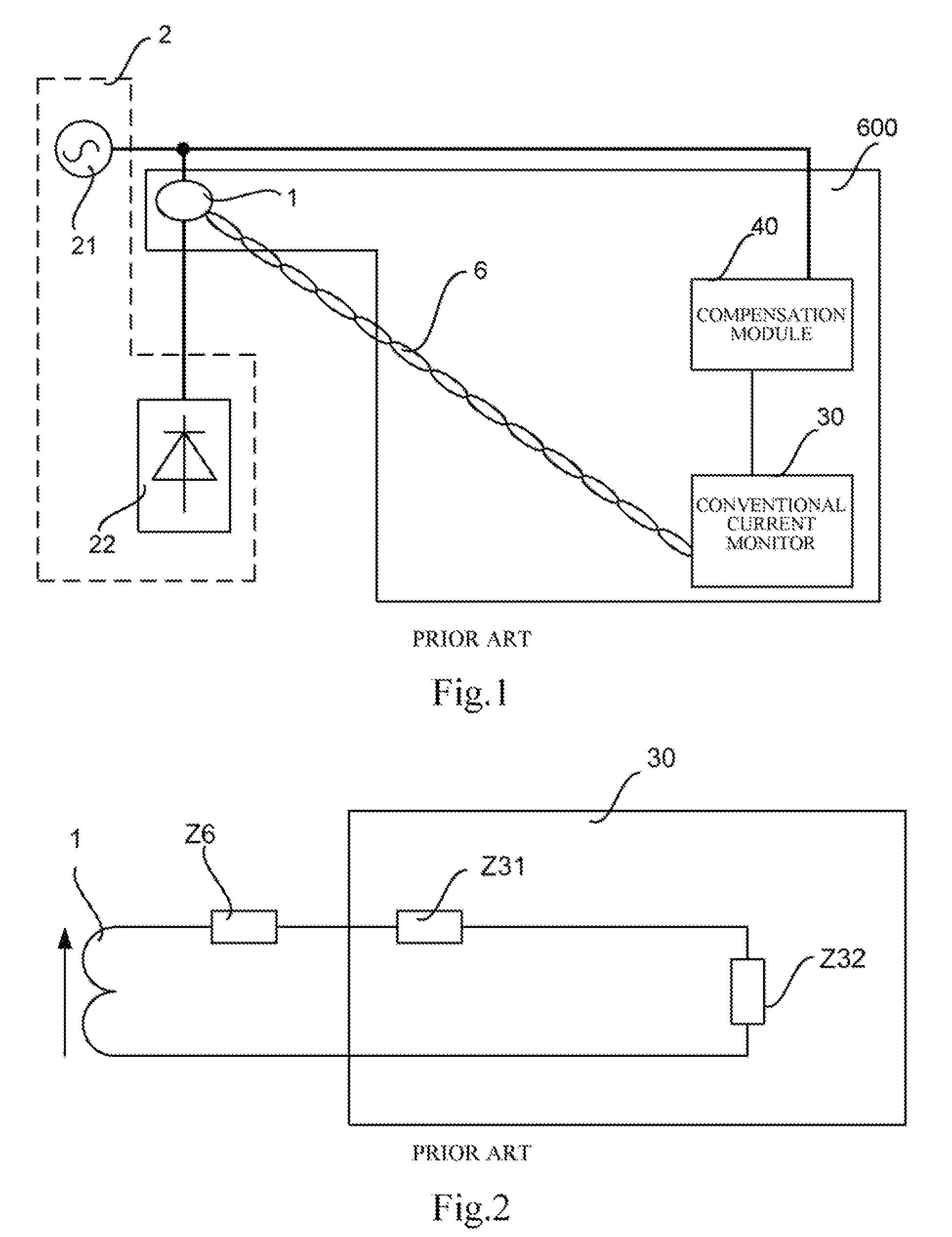
However, the conventional current monitor has following problems.
If an external current transformer has a large load which is likely to go beyond the secondary-side capacity, the current will be detected by the external current transformer inaccurately, and thereby the subsequent compensation effects of the compensation modules will be deteriorated.
However, one of the above two solutions will restrict the geographical location of the current monitor, and the other will limit the selective scope of the current monitor.
Thus, both of the two solutions are not ideal.

Method used


Image

  • Current monitor and electric power quality compensation system
  • Current monitor and electric power quality compensation system
  • Current monitor and electric power quality compensation system

Examples


first embodiment

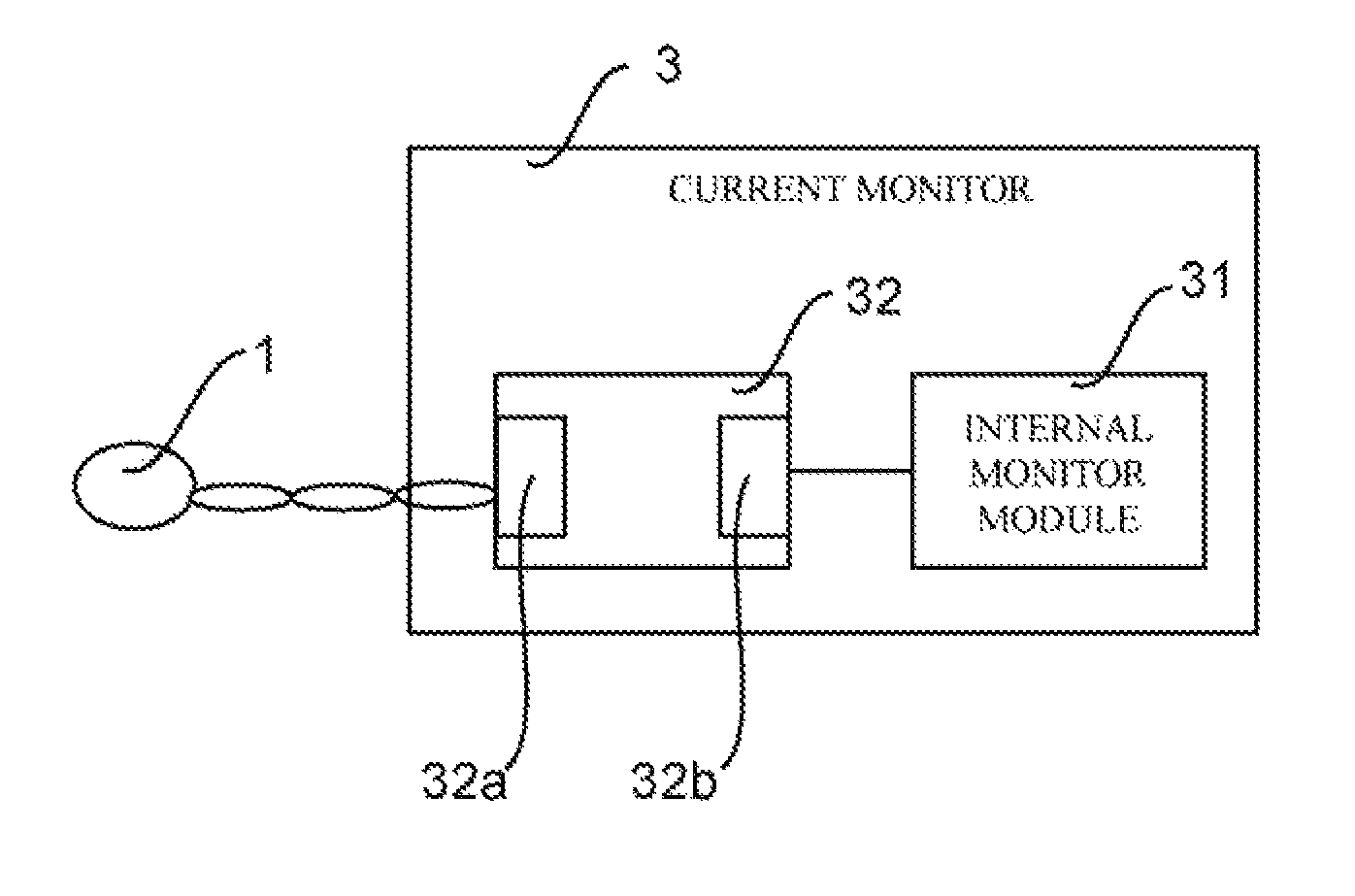
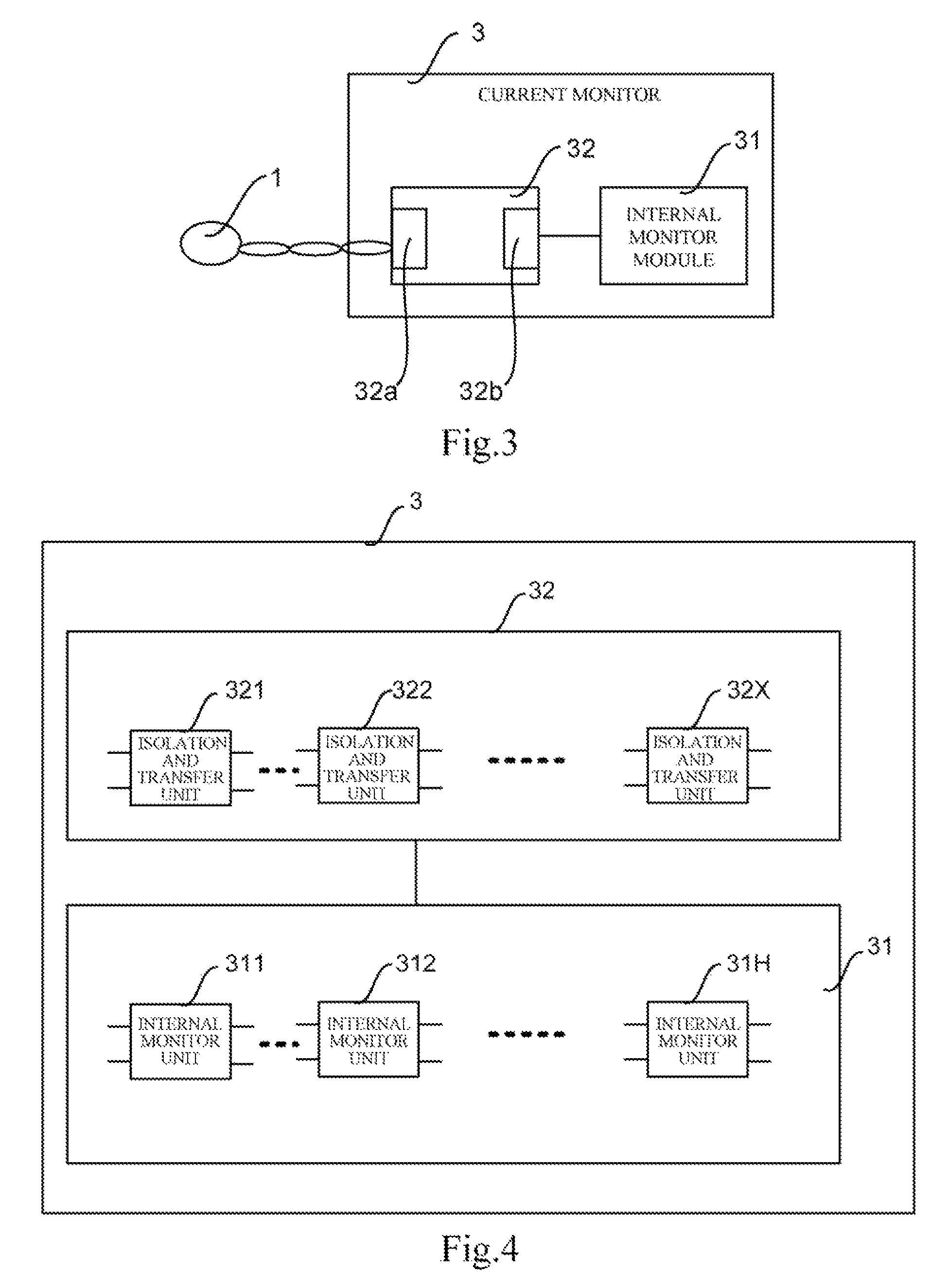
[0073]FIG. 3 illustratively shows a structure diagram of a current monitor according to the present application. The current monitor 3 includes an internal monitor module 31 and an isolation and transfer module 32. FIG. 3 also shows an external detection module 1 and illustrates the connection relationships between respective parts in the current monitor 3 and the external detection module 1.

[0074]The internal monitor module 31 outputs a measurement of current for characterizing a real-time electric power quality of an external power network based on a received detection current. The external detection module 1 detects a current of the external power network and outputs a first level detection current.

[0075]The isolation and transfer module 32 includes an input side 32a and an output side 32b which are electrically isolated from each other. The input side 32a is configured to be connected with the external detection module 1, for example, by an external cable. The output side 32b is...

second embodiment

[0079]FIG. 4 illustratively shows a structure diagram of a current monitor according to the present application. The isolation and transfer module 32 includes X number of isolation and transfer units 321, 322, . . . , 32X, and the internal monitor module 31 includes H number of internal monitor units 311, 312, . . . , 31H. X and H are natural numbers greater than or equal to 1. The internal monitor unit is used to output a measurement of current for characterizing a real-time electric power quality of an external power network based on a received detection current, which for example may be implemented by a transformer, and the structure and function of which is well known to those skilled in the art.

[0080]When X is greater than 1, the input sides of the X number of isolation and transfer units are connected in series. The X numbers of isolation and transfer units are configured to receive the first level detection current.

[0081]The output sides of the above isolation and transfer un...

third embodiment

[0087]In the embodiments of the present application, the isolation and transfer units may be implemented by current transformers. FIG. 5 illustratively shows a structure diagram of a current monitor according to the present application. In FIG. 5, the isolation and transfer module includes one isolation and transfer unit, which is, for example, one transfer current transformer 321 having a primary side as an input side of the isolation and transfer unit and a secondary side as an output side of the isolation and transfer unit respectively. The internal monitor module 31 includes H numbers of internal monitor units 311, 312, . . . , 31H, each of which has an input end including a pair of input terminals INa and INb. The input ends of the plurality of internal monitor units 311, 312, . . . 31H may be connected in series. Specifically, an input terminal INb of one internal monitor unit may be connected with an input terminal INa of an immediately next internal monitor unit such that th...


PUM


Abstract

It's disclosed a current monitor and an electric power quality compensation system. The current monitor includes: an internal monitor module configured to output a measurement of current for characterizing a real-time electric power quality of an external power network based on a received detection current, wherein an external detection module is used to detect a current of the external power network and output a first level detection current; and an isolation and transfer module including an input side and an output side electrically isolated from each other, wherein the input side is configured to be connected with the external detection module, and the output side is configured to be connected with the internal monitor module, the isolation and transfer module receives the first level detection current and outputs a second level detection current to the internal monitor module.

Description

CROSS REFERENCE TO RELATED APPLICATIONS[0001]The present application claims priority under 35 U.S.C. §119 to Chinese Patent Application No. 201210118826.9, filed on Apr. 20, 2012, the entire content of which is incorporated herein by reference.TECHNICAL FIELD[0002]The present application relates to current detection technologies, more particularly to a current monitor and an electric power quality compensation system.BACKGROUND[0003]With increasing requirements for suppressing reactive powers and harmonics, various electric power quality compensation systems have been widely used. These electric power quality compensation systems perform real-time detection on external power networks through external detection modules and internal current monitor so as to compensate electric power qualities of the external power networks.[0004]FIG. 1 illustratively shows an application example of an electric power quality compensation system in conventional technologies. In FIG. 1, the electric powe...

Claims


Application Information

Patent Timeline
Patent Type & Authority Patents(United States)
IPC IPC(8): G01R15/18G01R19/00G01R31/42H05B33/08H05B44/00
CPCG01R19/0092
Inventor CHEN, SHAOHUAYANG, YAPINGWANG, BIN
Owner DELTA ELECTRONICS INC
Learn More