Microwave-shielded tissue sensor probe

a tissue sensor and micro-wave shielding technology, applied in the field of systems and methods, can solve the problems of electromagnetic fields produced by the microwave ablation probe, reducing the accuracy and precision of tissue sensor probe measurements, and routine observation of thermal damage to most types of normal cells, so as to maximize the response time of thermal energy transfer and increase the speed and accuracy of temperature measurements.

Active Publication Date: 2015-11-24
COVIDIEN LP
View PDF130 Cites 38 Cited by
  • Summary
  • Abstract
  • Description
  • Claims
  • Application Information

AI Technical Summary

Benefits of technology

[0010]The disclosed tissue sensor probe and corresponding surgical ablation system increases the speed and accuracy of temperature measurements taken near an ablation probe during a microwave ablation procedure. This is achieved by shielding a temperature sensor within the probe from electromagnetic radiation produced by the microwave ablation probe and maximizing the response time of thermal energy transfer to the temperature sensor.

Problems solved by technology

However, at slightly elevated temperatures above the approximate range of 43° C. to 45° C. or with rapid bursts of elevated temperatures, thermal damage to most types of normal cells is routinely observed.
Changes in tissue impedance may cause an impedance mismatch between the probe and tissue, which may affect delivery of microwave ablation energy to targeted tissue.
If, however, the tissue sensor probe is positioned near a microwave ablation probe, the electromagnetic fields produced by the microwave ablation probe may reduce the accuracy and precision of the measurements of the tissue sensor probe either through direct thermal agitation of the thermal physics of the tissue sensor probe or through induced electrical current in the tissue sensor probe.
It is difficult, however, to predict the location and boundary of this electromagnetic field.
In addition, electromagnetic energy from other sources may interfere with the operation of the tissue sensor probe.

Method used


Image

  • Microwave-shielded tissue sensor probe
  • Microwave-shielded tissue sensor probe
  • Microwave-shielded tissue sensor probe

Examples


Embodiment Construction

[0027]Particular embodiments of the present disclosure will be described hereinbelow with reference to the accompanying drawings; however, it is to be understood that the disclosed embodiments are merely exemplary of the disclosure, which may be embodied in various forms. Well-known functions or constructions are not described in detail to avoid obscuring the present disclosure in unnecessary detail. Therefore, specific structural and functional details disclosed herein are not to be interpreted as limiting, but merely as a basis for the claims and as a representative basis for teaching one skilled in the art to variously employ the present disclosure in virtually any appropriately detailed structure.

[0028]In the drawings and in the descriptions that follow, the term “proximal,” as is traditional, shall refer to the end of the instrument that is closer to the user, while the term “distal” shall refer to the end that is farther from the user.

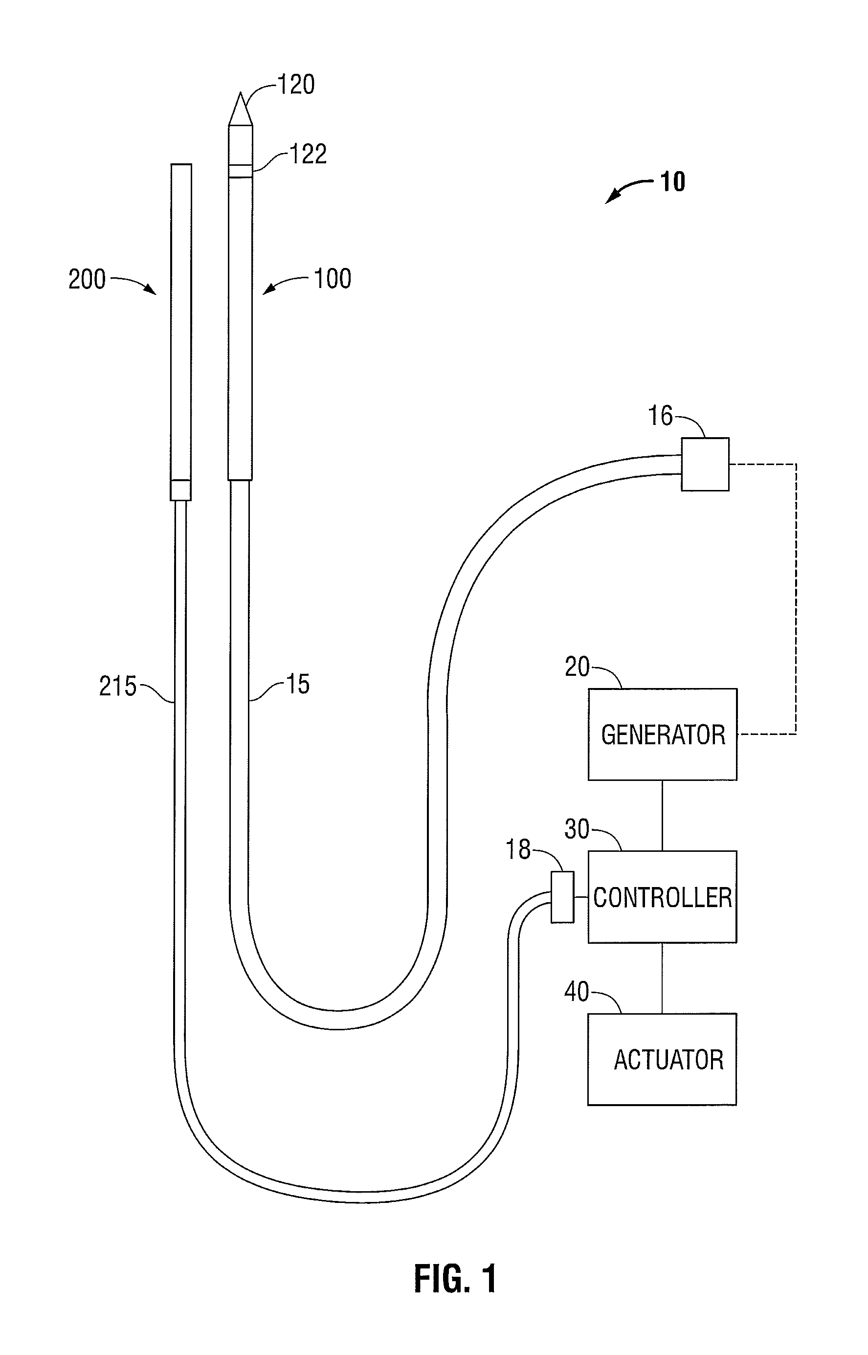
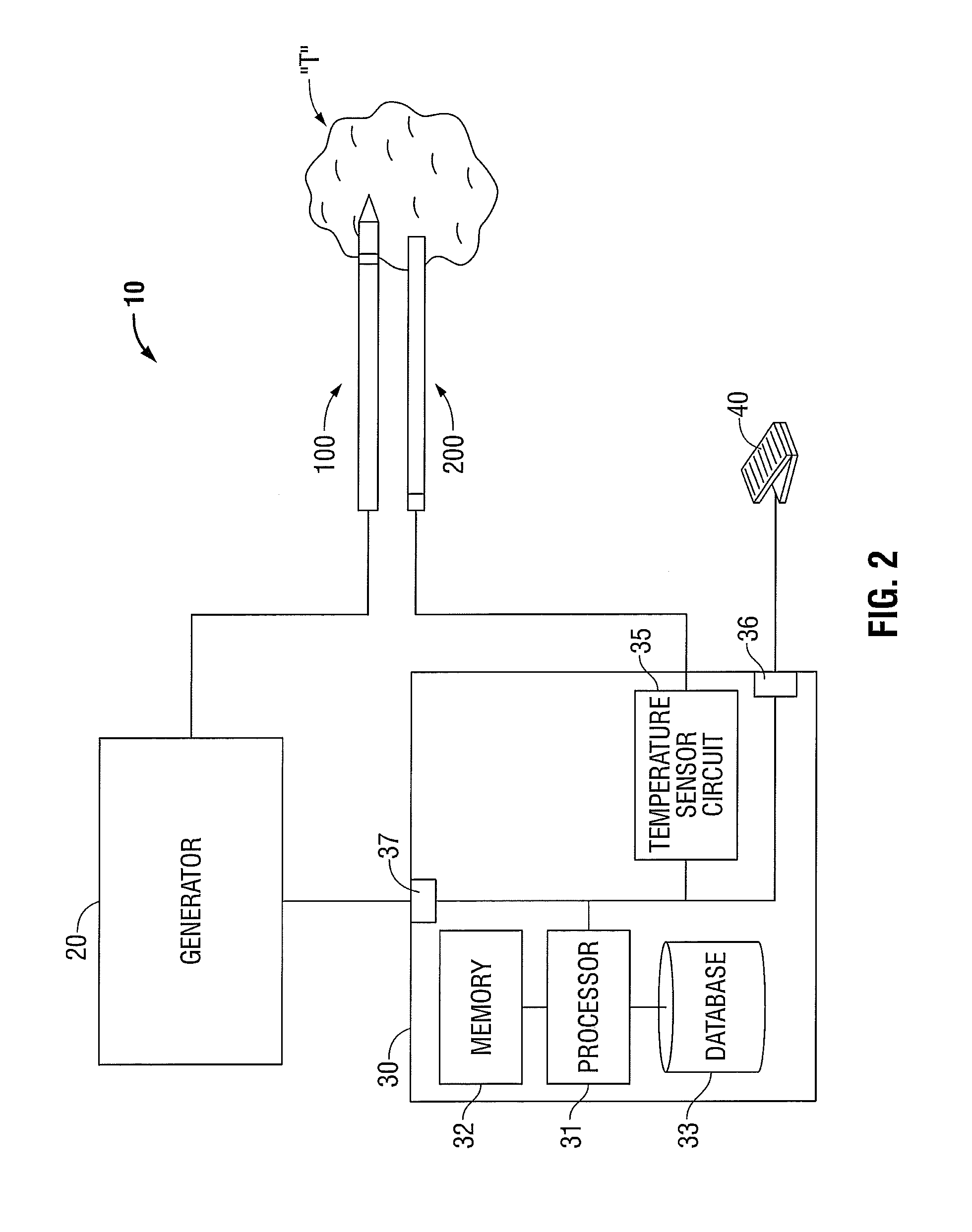
[0029]FIG. 1 shows an embodiment of a micr...


PUM


Abstract

A tissue sensor probe and corresponding electromagnetic surgical ablation system are disclosed. The system includes an ablation probe coupled to a generator, a controller coupled to the generator, and a tissue sensor probe coupled to the controller. The tissue sensor probe includes an electrically-conductive enclosure configured to shield a temperature sensor from electromagnetic radiation produced by the ablation probe. At least a portion of the electrically-conductive enclosure is made of a high thermal-conductivity material. A material of high thermal-conductivity is disposed in the electrically-conductive enclosure in thermal association with the thermally-conductive material of the electrically-conductive enclosure. The temperature sensor is disposed in the material of high thermal conductivity so as to electrically isolate the temperature sensor from the enclosure. The temperature sensor provides tissue temperature to the controller, which monitors tissue temperature to determine tissue status and activates and deactivates the generator based on the tissue status.

Description

BACKGROUND[0001]1. Technical Field[0002]The present disclosure relates to systems and methods for providing energy to biological tissue and, more particularly, to systems and methods for precisely sensing thermal parameters of tissue during a microwave ablation procedure.[0003]2. Background of Related Art[0004]Energy-based tissue treatment is well known in the art. Various types of energy (e.g., electrical, ultrasonic, microwave, cryogenic, thermal, laser, etc.) are applied to tissue to achieve a desired result. Electrosurgery involves application of high radio frequency electrical current to a surgical site to cut, ablate, coagulate or seal tissue. In monopolar electrosurgery, a source or active electrode delivers radio frequency energy from the electrosurgical generator to the tissue and a return electrode carries the current back to the generator. In monopolar electrosurgery, the source electrode is typically part of the surgical instrument held by the surgeon and applied to the ...

Claims


Application Information

Patent Timeline
Patent Type & Authority Patents(United States)
IPC IPC(8): A61B18/14A61B18/18A61B5/01A61B18/00
CPCA61B5/01A61B18/1815A61B2018/00642A61B2018/00702A61B2018/00797A61B2018/00809A61B2018/00815A61B2018/00821A61B2018/1861A61B2018/1869A61B2017/00017A61B2018/00095A61B2018/00791A61B2018/1823
Inventor BRANNAN, JOSEPH D.BONN, KENLYN S.
Owner COVIDIEN LP
Why Eureka
Try Eureka