Solids removal system and method

a technology of solids removal and solids, applied in sedimentation settling tanks, multi-stage water/sewage treatment, separation processes, etc., can solve the problems of inability to remove low-gravity solids, limited removal of conventional solids control equipment and methods, and increasing the problem of low-gravity solids buildup for operators, etc., to achieve the effect of improving the separation of solids

Active Publication Date: 2015-11-24
SOLIDS REMOVAL SERVICES LLC
View PDF27 Cites 6 Cited by
  • Summary
  • Abstract
  • Description
  • Claims
  • Application Information

AI Technical Summary

Problems solved by technology

However, during use, these drilling fluids can accumulate a build-up of low gravity colloidal materials, or low gravity solids (LGS) that can impart negative qualities to the drilling fluid.
In the oil and gas industry, low-gravity solids buildup is becoming an increasing problem for operators.
Conventional solids-control equipment and methods are limited in what they can remove, and presently cannot remove low-gravity solids smaller than 8 to 10 microns that accumulate and degrade the performance of costly oil- and synthetic-base drilling fluids.
Despite these cautions, solids contained in the RDFs can plug formation pore throats and cause reduced permeability and formation damage if those solids cannot be adequately removed.
Even with an aggressive, but conventional, solids-control process, some solids and bridging agent particles can degrade and become so small as to slip through the solids-control devices.
As a consequence, the operator ends up with drilling fluids that are contaminated and must be disposed of or diluted with new mud to create useable product.
Compliance with disposal regulations makes disposal a significant and expensive problem.
However, the dilution process itself requires 3× to 4× the fluid volume and therefore taxes the available capacities of a mud plant, in addition to increasing costs associated with handling, transportation and storage.
Dilution of mud also presents a virtually insurmountable problem on offshore rigs where there typically does not exist sufficient excess fluid storage capacity.
The only other solution is to build new mud thereby increasing costs on two fronts—new mud, and disposal of old mud.

Method used


Image

  • Solids removal system and method
  • Solids removal system and method
  • Solids removal system and method

Examples


Embodiment Construction

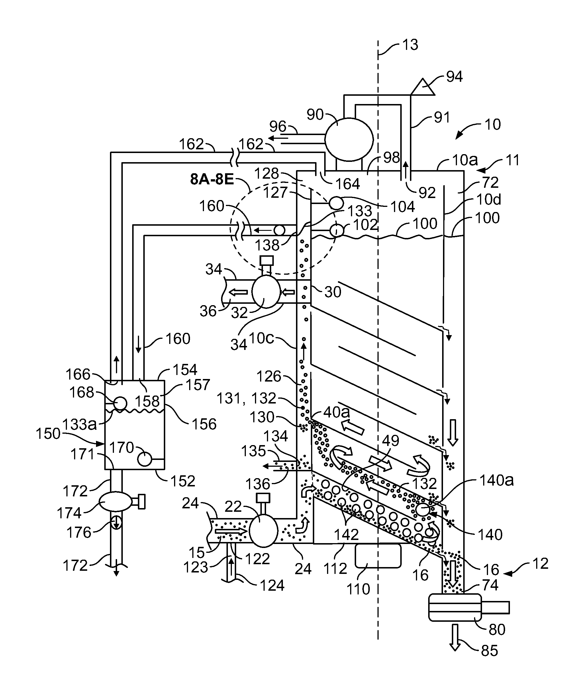
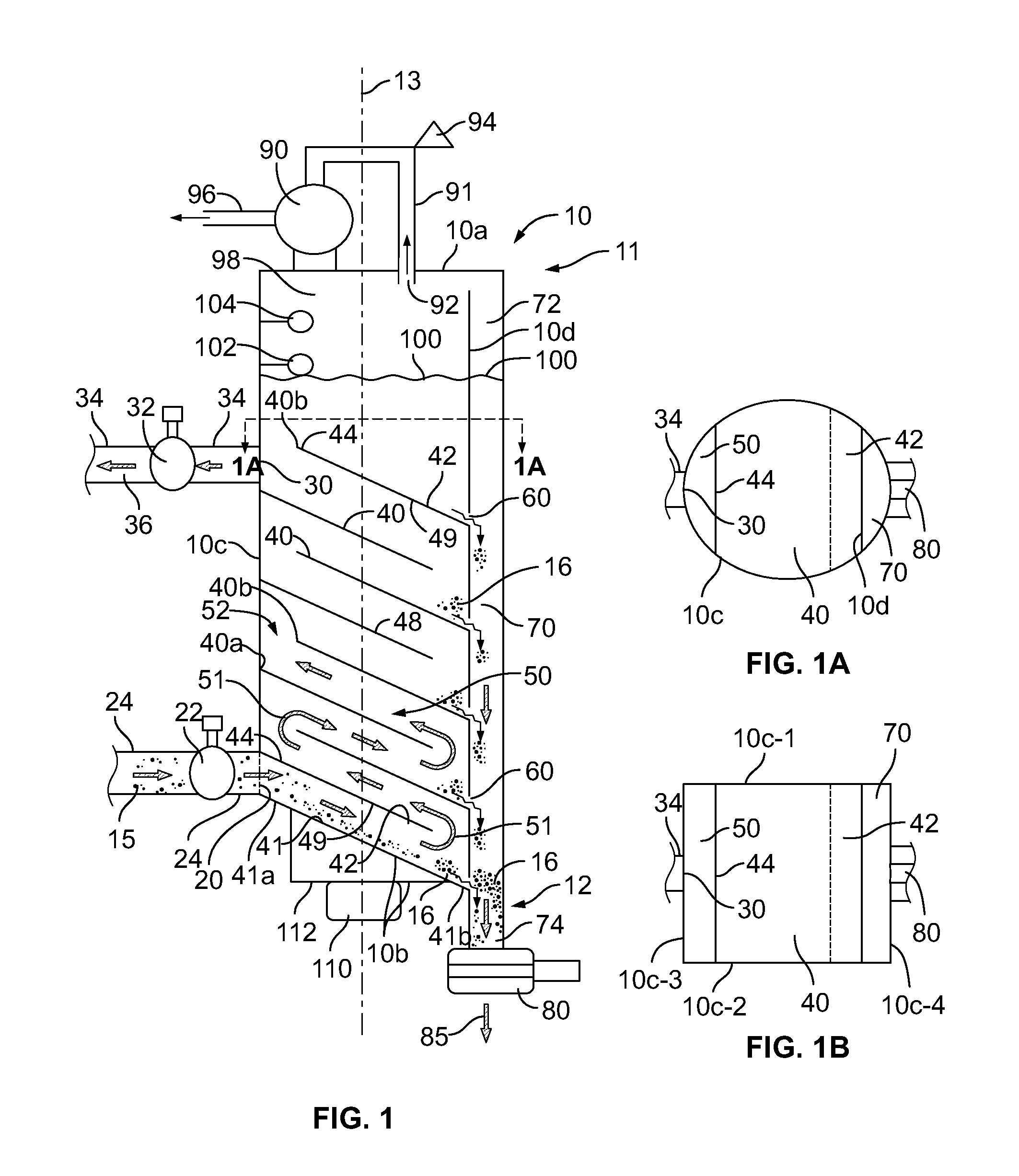
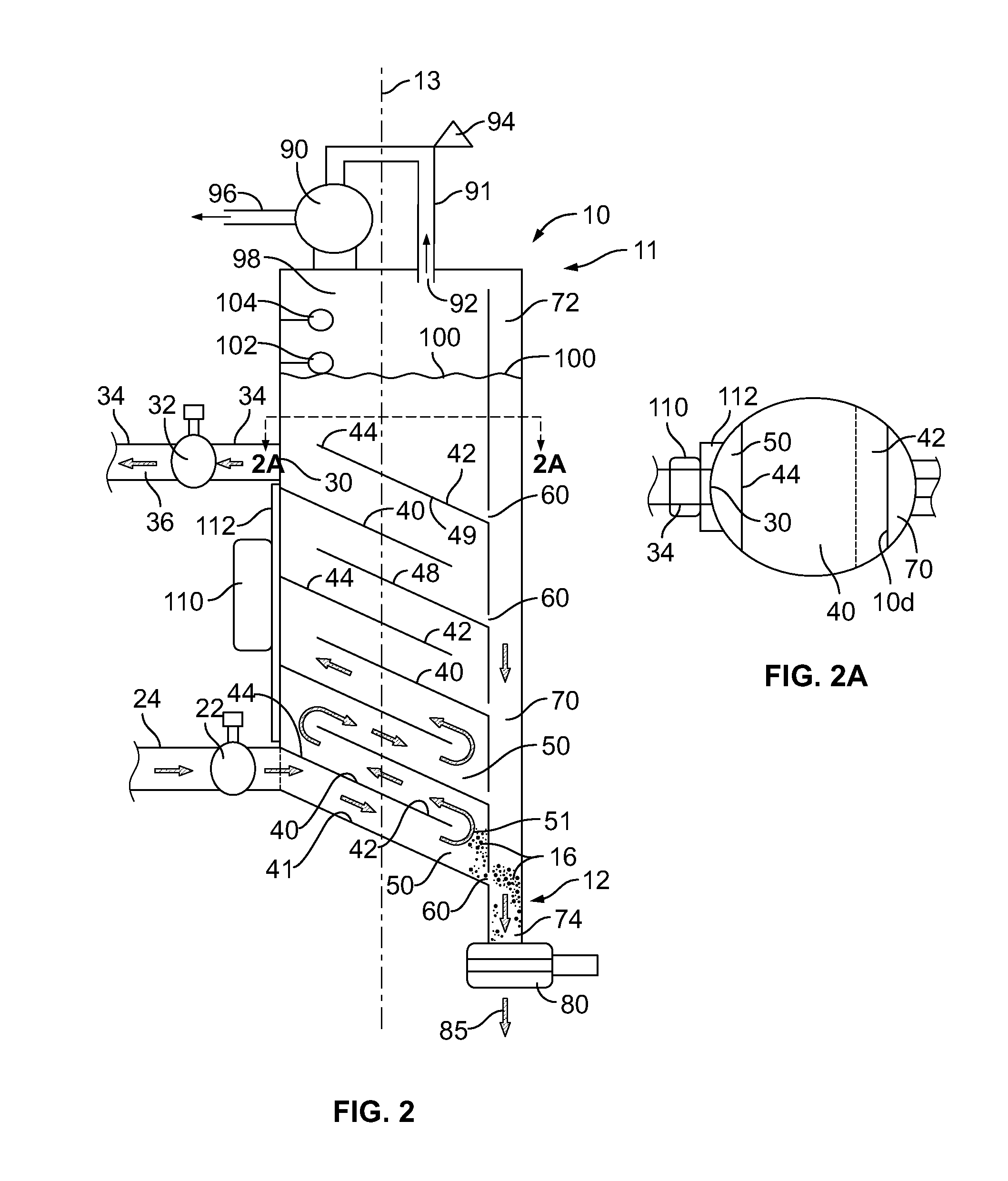
[0084]Reference is now made to the drawings which depict preferred embodiments of the present invention, but are not drawn to scale. Referring now to FIGS. 1-5, there are shown partial cross-sectional views of various separation tower 10 embodiments in accordance with the present invention for use in the treatment of solids laden water 14.

[0085]In a preferred embodiment, the separation tower 10 is oriented vertically along a longitudinal axis 13, and has an upper end 11 and a lower end 12. The vessel can be any general shape, but a preferred shape would be cylindrical or rectangular. The vessel construction is designed to be a closed system that can withstand the maximum pressure that can be pulled by a vacuum, e.g., approx. 29.92 inches of Mercury.

[0086]A source of contaminated liquid (e.g., a solids / gas laden liquid) 15 is conveyed in the inlet conduit 24 and introduced into the separator 10 via inlet 20. The inlet conduit is in fluid communication between the source of contaminat...


PUM

PropertyMeasurementUnit
densityaaaaaaaaaa
angleaaaaaaaaaa
angleaaaaaaaaaa

Abstract

The system and method is directed to improved separation or clarification of solids from a solids-laden liquid, including the removal of low gravity solids. A liquid to be treated is introduced into the inlet of a solid-liquid separator modified to include one or more sources of vibrational energy. The liquid is directed through a conduit within the separator. This conduit can be configured into a tortuous flow path to assist in the separation of solids from the liquid, the tortuous path being interconnected between two separation towers. Vibrational energy and gas sparging is applied to the flow path. As solids fall out of solution, they are collected. The clarified liquid is also collected. A vacuum can be applied to the system to assist in moving the solid-liquid mixture through the system and to provide vacuum clarification. Electrocoagulation electrodes can also be employed.

Description

CROSS-REFERENCE TO RELATED APPLICATIONS[0001]This application is a continuation-in-part of U.S. Nonprovisional patent application Ser. No. 13 / 239,338 filed Sep. 21, 2011, now U.S. Pat. No. 8,691,097, which is a continuation-in-part of U.S. Nonprovisional patent application Ser. No. 12 / 888,329 filed on Sep. 22, 2010, now U.S. Pat. No. 8,337,706, which in turn is a continuation-in-part of U.S. Nonprovisional patent application Ser. No. 12 / 250,535 filed on Oct. 13, 2008, (now abandoned), which in turn claims the benefit of the filing date of and priority to U.S. Provisional Application Ser. No. 60 / 979,858 entitled “Solids Removal System and Method” and filed Oct. 14, 2007. The contents of said applications are incorporated by reference herein in their entireties.STATEMENT REGARDING FEDERALLY SPONSORED RESEARCH OR DEVELOPMENT[0002]Not Applicable.BACKGROUND OF THE INVENTION[0003]The present invention is directed generally to a method and apparatus for removing solids from a solid-liquid ...

Claims


Application Information

Patent Timeline
Patent Type & Authority Patents(United States)
IPC IPC(8): B01D21/02B01D17/028B01D21/28B01D19/00B01D17/02B01D21/00B01D21/24B01D21/34C02F1/463C02F1/34C02F1/36C02F1/00
CPCB01D19/0063B01D19/0078B01D21/0024B01D19/0036B01D17/0211B01D17/0214B01D19/0042B01D21/0042B01D21/0057B01D21/0066B01D21/0084B01D21/2461B01D21/2494B01D21/283B01D21/34C02F1/463B01D21/0039B01D2221/04C02F1/34C02F1/36C02F2001/007C02F2201/4613C02F2301/02C02F2301/028C02F2301/063B01D21/302C02F1/24C02F1/302C02F9/00
Inventor MCCABE, DERALD L.
Owner SOLIDS REMOVAL SERVICES LLC
Why Eureka
Try Eureka