Pneumatic spanner structure

a technology of pneumatic spanners and spanners, which is applied in the direction of manufacturing tools, portable power-driven tools, drilling pipes, etc., can solve the problems of large buffer space and unstable structure, and achieve the effect of stable and compact structure, extended service life of the whole structur

Inactive Publication Date: 2015-11-24
LIN CHUN YU
View PDF15 Cites 1 Cited by
  • Summary
  • Abstract
  • Description
  • Claims
  • Application Information

AI Technical Summary

Benefits of technology

[0009]The primary object of the present invention is to provide a pneumatic spanner structure which comprises a head body, a link bevel gear unit, a hit unit and a driving handle. A connection positioning hole of the axle portion of a motor link bevel gear post is adapted for connection of a driving motor axle portion at the open end of the driving handle. A guide post with a second rotation ring of a hit unit link bevel gear plate is positioned in a first positioning trough of an accommodation head seat portion of a head body. A link axle portion of the hit unit is engaged in an engaging hole of a second positioning trough of the hit unit link bevel gear plate. A head portion extends out of a lid of the accommodation head seat portion of the head body. The driving motor axle portion at the open end of the driving handle drives the motor link bevel gear post and the hit unit link bevel gear plate of the link bevel gear unit. The hit unit link bevel gear plate links the hit unit. The link bevel gear unit enhances and transmits the force to the hit unit. The hit unit applies the acting force on a workpiece. The hit unit doesn't need a buffer space for actuation and the force is indirect. The link bevel gear unit is a deceleration device to extend the service life of the whole structure. The output force is more powerful than the prior art, providing a stable and compact structure.

Problems solved by technology

Through the hit unit to drive the gear, the impact of the hit unit centralizes the press on the gear post and the gear plate to damage the gear post and the gear plate so the structure is unstable.
This structure needs larger buffer space to consume the efficiency of the hit unit.

Method used


Image

  • Pneumatic spanner structure
  • Pneumatic spanner structure
  • Pneumatic spanner structure

Examples


Embodiment Construction

[0016]Embodiments of the present invention will now be described, by way of example only, with reference to the accompanying drawings.

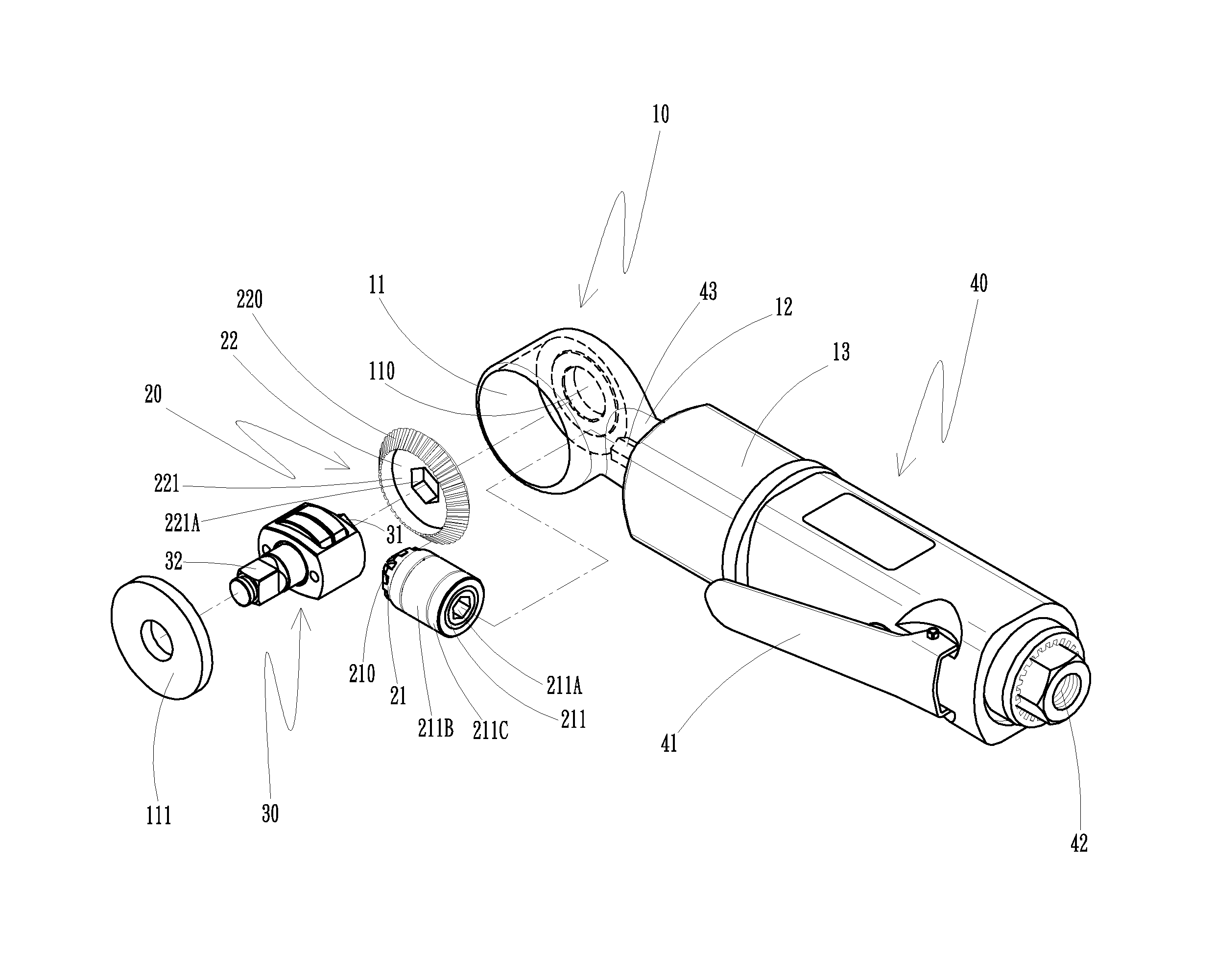
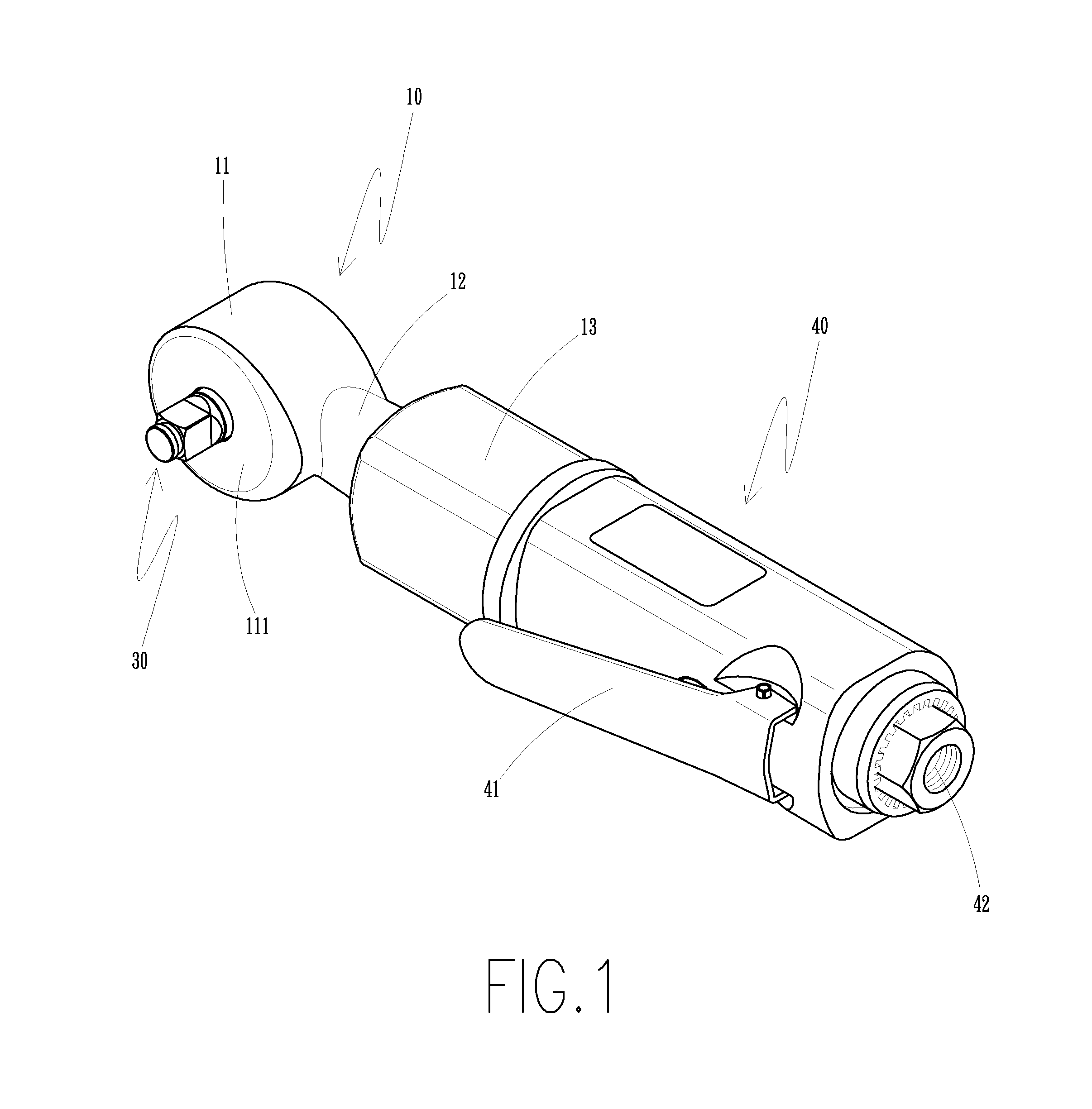
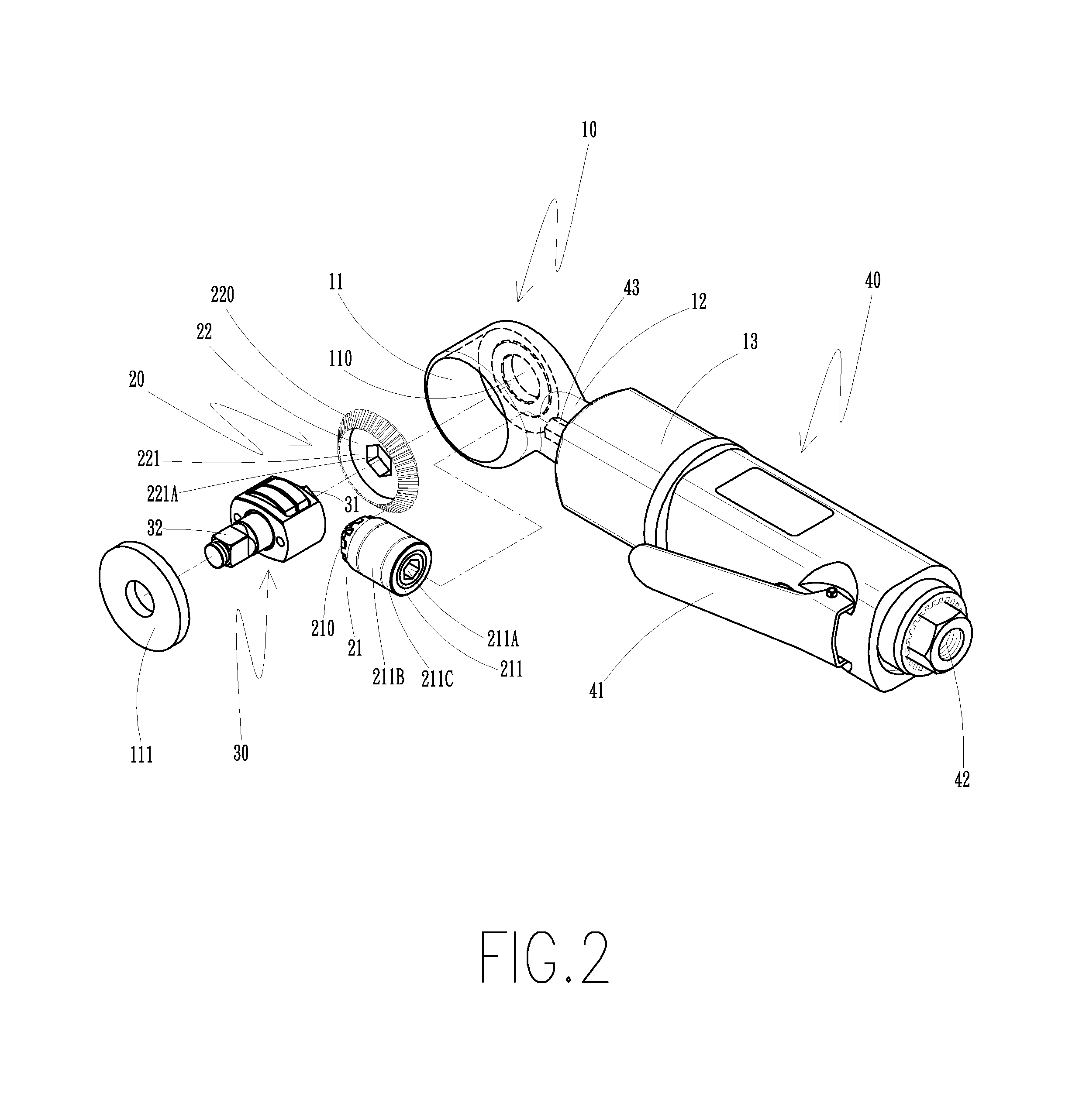
[0017]FIG. 1 is a perspective view of the present invention. FIG. 2 is an exploded view of the present invention. FIG. 3 is a partial perspective view of the present invention. FIG. 4 is a partial sectional view of the present invention. As shown in FIG. 1 to FIG. 4, the pneumatic spanner structure of the present invention comprises a head body (10), a link bevel gear unit (20), a hit unit (30) and a driving handle (40).

[0018]The head body (10) comprises an accommodation head seat portion (11), a hollow neck portion (12) and an accommodation connection seat portion (13). The accommodation head seat portion (11), the hollow neck portion (12) and the accommodation connection seat portion (13) communicate with each other. The accommodation head seat portion (11) has a first positioning trough (110) therein. The accommodation head seat portion (11) is cov...


PUM


Abstract

A pneumatic spanner structure includes a head body, a link bevel gear unit, a hit unit and a driving handle. A driving motor axle portion at an open end of the driving handle drives a motor link bevel gear post and a hit unit link bevel gear plate of the link bevel gear unit. The hit unit link bevel gear plate links the hit unit. The link bevel gear unit enhances and transmits the force to the hit unit. The hit unit applies the acting force on a workpiece. The hit unit doesn't need a buffer space for actuation and the force is indirect. The link bevel gear unit is a deceleration device to extend the service life of the whole structure. The output force is more powerful than the prior art, providing a stable and compact structure.

Description

[0001]The current application claims a foreign priority to the patent application of Taiwan No. 101204393 filed on Mar. 12, 2012.BACKGROUND OF THE INVENTION[0002]1. Field of the Invention[0003]The present invention relates to a pneumatic spanner structure, and more particularly, to a pneumatic spanner structure for a pneumatic tool.[0004]2. Description of the Prior Art[0005]A conventional pneumatic spanner, as shown in FIG. 6, comprises a hit unit (50) to drive a gear post (51). The gear post (51) drives a bevel gear plate (52) to link a spanner axle (53). However, the conventional pneumatic spanner has the following shortcomings.[0006]1. Unstable structure: The hit unit drives the gear post. The gear post drives the bevel gear plate to link the spanner axle. The force is direct applied to the gear post and the gear plate to wear and tear the teeth of the gear post and the gear plate. Through the hit unit to drive the gear, the impact of the hit unit centralizes the press on the gea...

Claims


Application Information

Patent Timeline
Patent Type & Authority Patents(United States)
IPC IPC(8): E21B3/00E21B19/18B25B21/02B25B21/00E21B17/22E21B19/16B25F5/00
CPCB25F5/005B25B21/004B25B21/02
Inventor LIN, CHUN YU
Owner LIN CHUN YU
Why Eureka
Try Eureka