Impact tool assembly and method of assembling same

a tool and impact technology, applied in the field of tool assembly, can solve the problems of increasing the operational cost of the compaction tool, requiring a high level of exertion from the user, and heavy weight of the known compaction tool

Inactive Publication Date: 2015-12-08
DYNAMATIC SOLUTIONS
View PDF37 Cites 11 Cited by
  • Summary
  • Abstract
  • Description
  • Claims
  • Application Information

AI Technical Summary

Problems solved by technology

These tamping tools require a high level of exertion from the user by requiring the user to repeatedly lift the tamping tool above the ground to deliver the compacting blow.
These compaction tools require an air supply and / or fuel to enable operation of the compaction tools, which increases an operational cost of the compaction tool.
In addition, known compaction tools are heavy, and require significant effort from the use to control the direction and operation of the compaction tool.

Method used


Image

  • Impact tool assembly and method of assembling same
  • Impact tool assembly and method of assembling same
  • Impact tool assembly and method of assembling same

Examples


Embodiment Construction

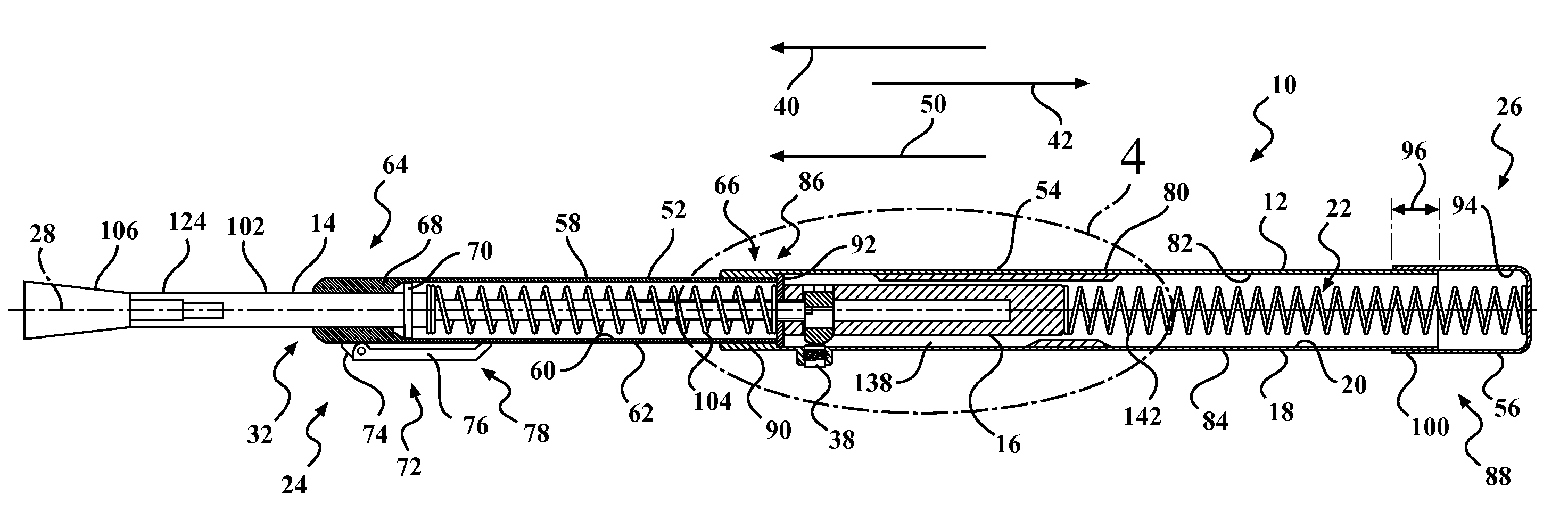
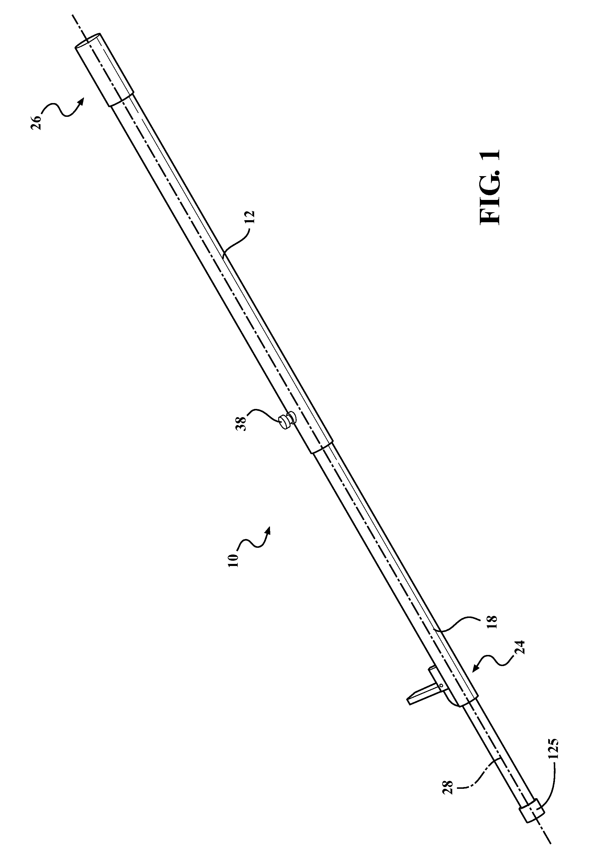
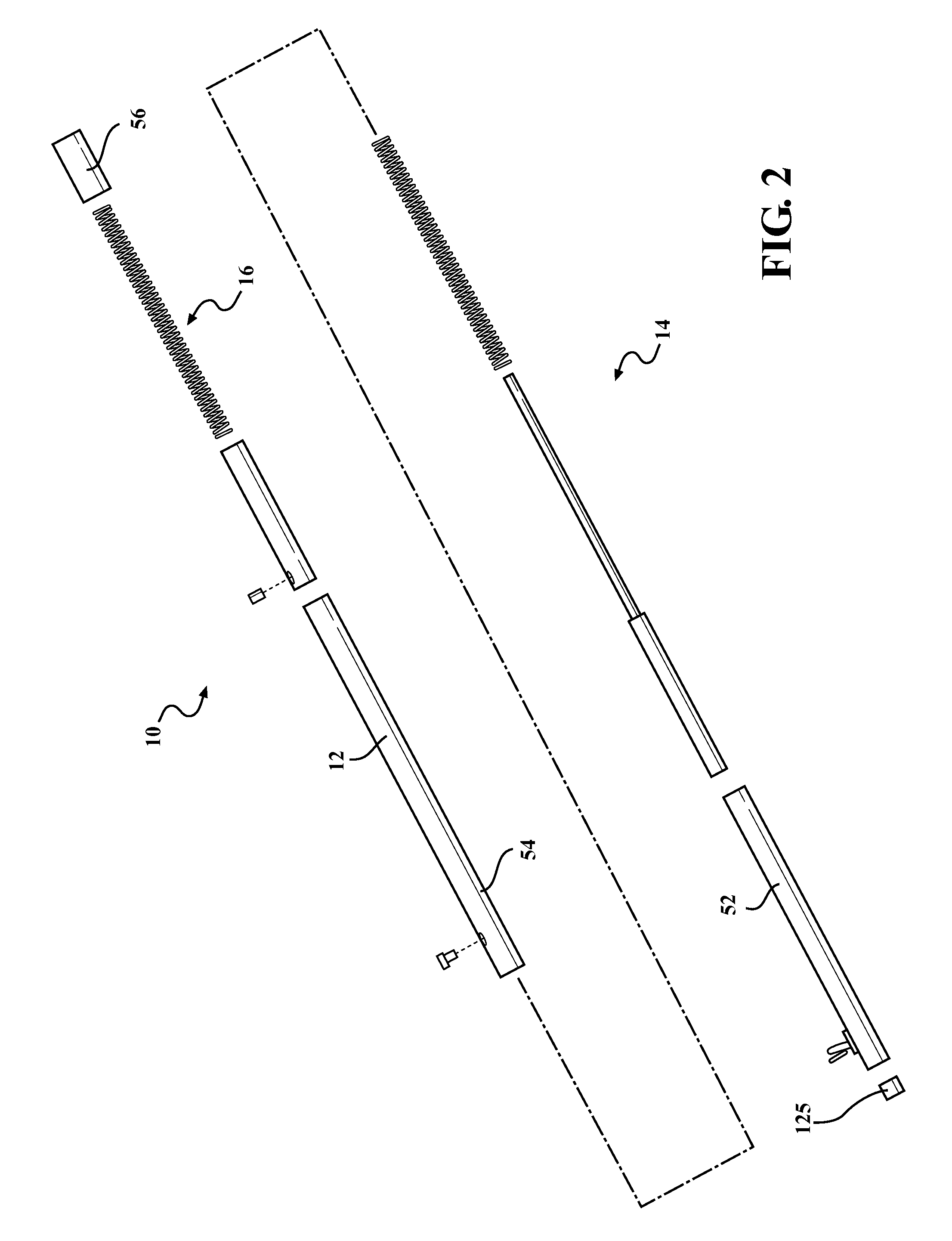
[0024]The exemplary apparatus and methods described herein overcome at least some disadvantages of known compaction tools by providing a tool assembly that enables a user to manually operate the tool assembly to deliver an axial force to a ground surface. The tool assembly that is selectively operable between a tamping mode wherein the tool assembly impacts a first axial force to a ground surface, and a driving mode, wherein the tool assembly imparts the first axial force and a second axial force to the ground surface. In addition, the tool assembly includes a rod assembly that is slideably coupled to a housing assembly, and is configured to bias the housing assembly from the ground surface to enable the user to operate the tool assembly in a reciprocating motion, and to reduce an effort required to compact the ground surface over known compaction tools. By providing a tool assembly that operates in a plurality of operational modes, and that is operated in a reciprocating motion, th...


PUM

PropertyMeasurementUnit
axial forceaaaaaaaaaa
areaaaaaaaaaaa
forceaaaaaaaaaa

Abstract

A tool assembly is described herein. The tool assembly includes a housing assembly that includes a first end, a second end, and an inner surface that defines a cavity that extends between the first end and the second end along a longitudinal axis. A rod assembly is slideably coupled to the housing assembly and is orientated within the housing cavity such that a portion of the rod assembly extends outwardly from the housing first end. An impact assembly is positioned within the housing cavity and is orientated between the rod assembly and the housing second end. The tool assembly is operable in a first operating mode wherein the rod assembly is movable with respect to the impact assembly, and a second operating mode wherein the impact assembly contacts the rod assembly to move the rod assembly outwardly from the housing.

Description

CROSS-REFERENCE TO RELATED APPLICATIONS[0001]This application claims the benefit of U.S. Provisional Application No. 61 / 485,042, filed May 11, 2011, the disclosure of which is incorporated herein by reference.FIELD OF THE INVENTION[0002]The present invention relates generally to a tool assembly, and more particularly, to a tool assembly that is operable between a tamping mode of operation and a driving mode of operation.BACKGROUND OF THE INVENTION[0003]At least some known tamping tools include a tamping plate that is coupled to a rod assembly. Known tamping tools are configured to enable the user to lift the tamping tool above a ground surface and thrust the tamping tool into the ground surface to impart an axial force to the ground surface to facilitate compacting the ground surface. These tamping tools require a high level of exertion from the user by requiring the user to repeatedly lift the tamping tool above the ground to deliver the compacting blow.[0004]At least some known co...

Claims


Application Information

Patent Timeline
Patent Type & Authority Patents(United States)
IPC IPC(8): E02D7/04
CPCE02D7/04Y10T29/4984
Inventor LUSK, JEREMY
Owner DYNAMATIC SOLUTIONS
Why Eureka
Try Eureka