Check patentability & draft patents in minutes with Patsnap Eureka AI!

Two-wire transmitter starter circuit and two-wire transmitter including the same

a two-wire transmitter and starter circuit technology, applied in transmission systems, instruments, power conversion systems, etc., can solve problems such as complicated circuit configuration illustrated in fig. 4 and achieve the effect of simplifying the circuit configuration of the two-wire transmitter starter circui

Active Publication Date: 2015-12-15
YOKOGAWA ELECTRIC CORP
View PDF13 Cites 0 Cited by
  • Summary
  • Abstract
  • Description
  • Claims
  • Application Information

AI Technical Summary

Benefits of technology

[0032]According to an aspect of the present invention, the constant current source operating before a power supply starts up is unnecessary, and the circuit configuration of the two-wire transmitter starter circuit can be simplified.

Problems solved by technology

Therefore, the circuit configuration illustrated in FIG. 4 is complicated.

Method used


Image

  • Two-wire transmitter starter circuit and two-wire transmitter including the same
  • Two-wire transmitter starter circuit and two-wire transmitter including the same
  • Two-wire transmitter starter circuit and two-wire transmitter including the same

Examples


Embodiment Construction

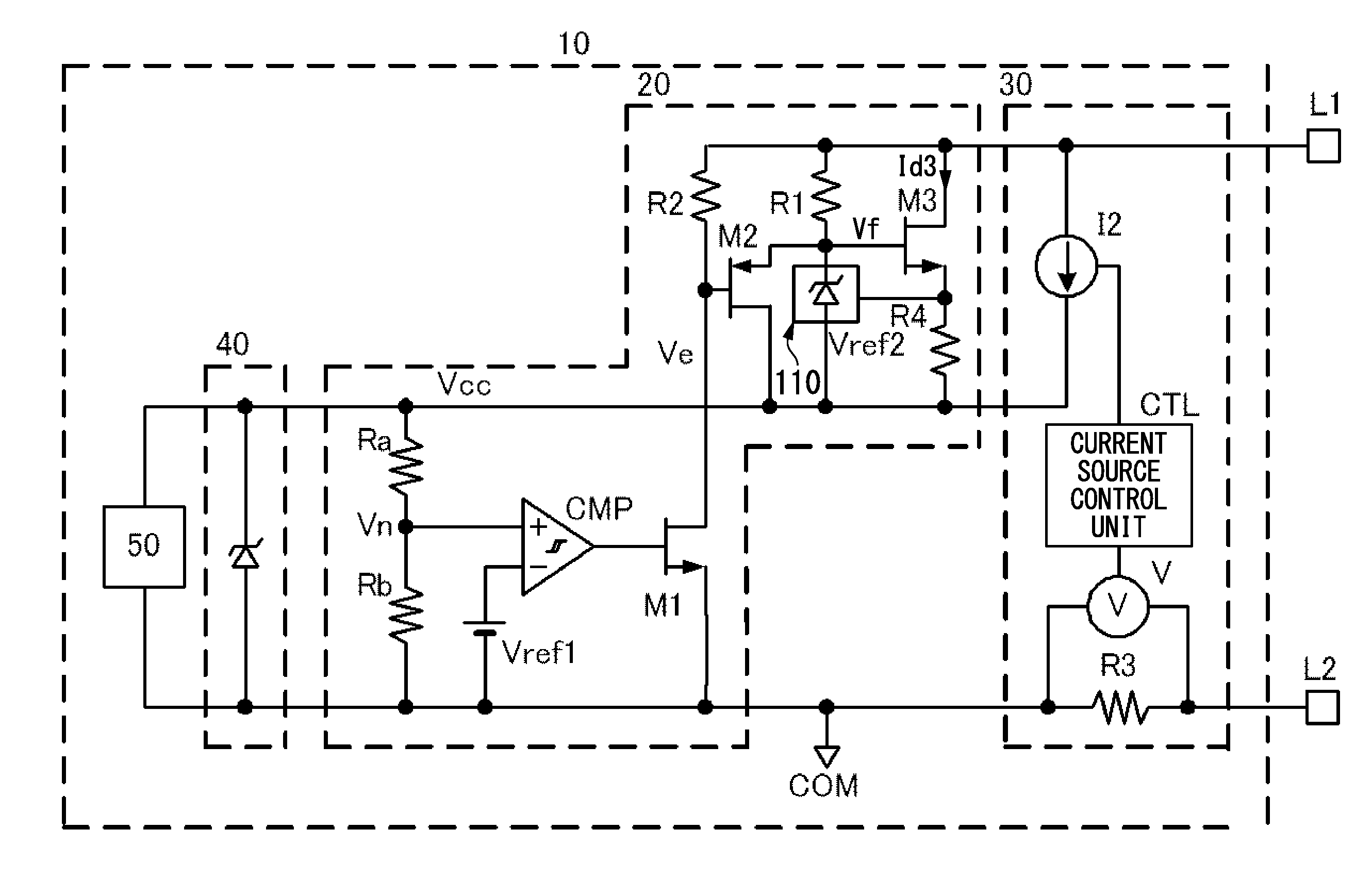
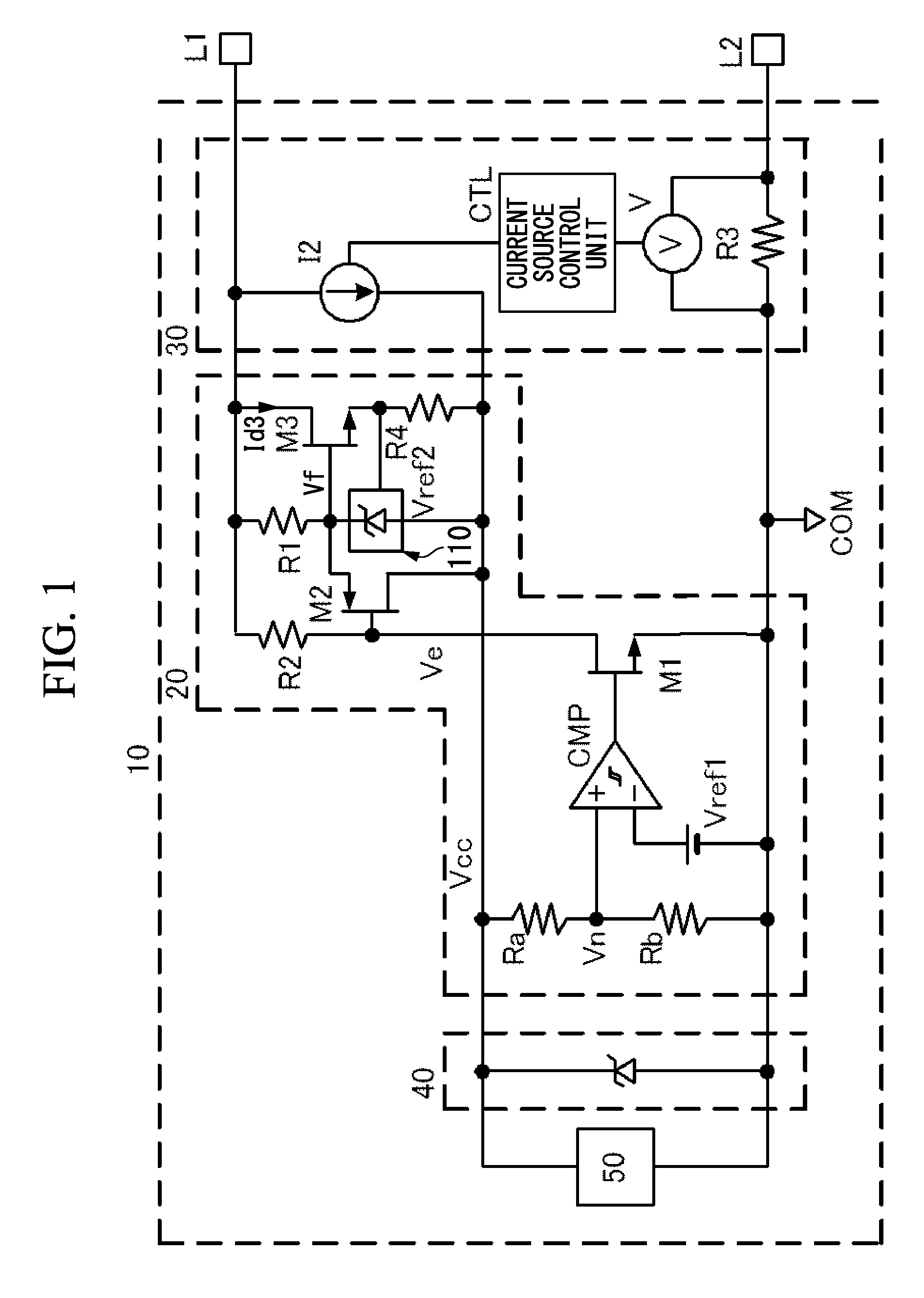
[0041]Hereinafter, one aspect of the present invention will be described with reference to the drawings. FIG. 1 is a block diagram illustrating an embodiment of the present invention, and the same parts as those in FIG. 4 are denoted by the same reference numerals. A two-wire transmitter 10 of the embodiment includes a starter circuit 20, a current conversion unit 30, a power supply unit 40, and an internal circuit 50. The starter circuit 20 is configured to secure supply of power and to improve stability of the transmitter 10 at the time of start-up. The current conversion unit 30 is configured to convert a detection signal of a sensor to a DC current ranging from 4 to 20 mA. The power supply unit 40 is configured to generate a predetermined voltage, and to supply the voltage to the current conversion unit 30, the internal circuit 50 and the like. The internal circuit 50 is configured to perform signal processing on an electrical signal from the sensor, and to send the signal to th...


PUM


Abstract

A two-wire transmitter starter circuit is configured to stably supply power at the time of start-up. The two-wire transmitter starter circuit includes a starter current generation circuit. The starter current generation circuit is connected in parallel with a current conversion unit configured to convert a detection signal of a sensor to a predetermined DC current. The starter current generation circuit includes a first series circuit where a first resistor and a shunt regulator are connected in series, and a second series circuit where a switching element and a second resistor are connected in series. The shunt regulator includes a first control terminal connected to a connection point of the switching element and the second resistor. The switching element includes a second control terminal connected to a connection point of the first resistor and the shunt regulator.

Description

BACKGROUND OF THE INVENTION[0001]1. Field of the Invention[0002]The present invention relates to a two-wire transmitter starter circuit and a two-wire transmitter including the two-wire transmitter starter circuit. More specifically, the present invention relates to a two-wire transmitter starter circuit including a simplified circuit configuration and a two-wire transmitter including the two-wire transmitter starter circuit.[0003]Priority is claimed on Japanese Patent Application No. 2012-250104, filed Nov. 14, 2012, the content of which is incorporated herein by reference.[0004]2. Description of Related Art[0005]Generally, a two-wire transmitter includes a starter circuit to secure supply of power and achieve stability of the transmitter at the time of start-up. FIG. 4 is a circuit diagram illustrating an example of a two-wire transmitter starter circuit of the related art.[0006]In FIG. 4, a two-wire transmitter 10 is connected to two-wire type transmission lines L1 and L2. The tw...

Claims


Application Information

Patent Timeline
Patent Type & Authority Patents(United States)
IPC IPC(8): H02M1/36G05F3/08G08C19/02G08C19/00
CPCH02M1/36G05F3/08G08C19/00G08C19/02
Inventor HATORI, DAISUKE
Owner YOKOGAWA ELECTRIC CORP
Features
  • R&D
  • Intellectual Property
  • Life Sciences
  • Materials
  • Tech Scout
  • Unparalleled Data Quality
  • Higher Quality Content
  • 60% Fewer Hallucinations
Learn More